A modular electric control cabinet assembly vehicle

A technology for electric control cabinets and assembling vehicles, applied in switchgear, electrical components and other directions, can solve the problems of affecting the assembly of high and low voltage control modules, occupying large space, inaccurate positioning, etc., to facilitate transportation and assembly, improve assembly efficiency, The effect of reducing flexibility

Active Publication Date: 2021-06-01
CHINA NUCLEAR ELECTRICAL CO LTD
View PDF9 Cites 0 Cited by
  • Summary
  • Abstract
  • Description
  • Claims
  • Application Information

AI Technical Summary

Problems solved by technology

[0002] The electrical control cabinet is composed of a high and low voltage control module, a box body and various corresponding functional components. The high and low voltage control module is generally an integral structure, and it is the heaviest Carrying the high and low voltage control modules during the process will increase the difficulty of protecting the high and low voltage control modules, and at the same time it is inconvenient to carry the electrical control cabinet. Therefore, the existing method is to assemble the high and low voltage control modules into the electric control cabinet through on-site assembly. This method greatly reduces the difficulty of the overall transportation of the electric control cabinet
[0003] The existing assembly vehicle used for assembling the height control module of the electric control cabinet cannot be folded, so it will occupy a large space during transportation. At the same time, the existing assembly vehicle still has the phenomenon of inaccurate positioning, which affects The assembly of high and low voltage control modules, and secondly, the existing component vehicles still cannot adapt to the assembly of electric control cabinets of different heights, which increases the difficulty of on-site assembly of electric control cabinets

Method used


Image

  • A modular electric control cabinet assembly vehicle
  • A modular electric control cabinet assembly vehicle
  • A modular electric control cabinet assembly vehicle

Examples


Embodiment Construction

[0052] In order to make the purpose, technical solutions and advantages of the embodiments of the present invention clearer, the technical solutions in the embodiments of the present invention will be clearly and completely described below in conjunction with the drawings in the embodiments of the present invention. Obviously, the described embodiments It is a part of embodiments of the present invention, but not all embodiments. The components of the embodiments of the invention generally described and illustrated in the figures herein may be arranged and designed in a variety of different configurations.

[0053] Accordingly, the following detailed description of the embodiments of the invention provided in the accompanying drawings is not intended to limit the scope of the claimed invention, but merely represents selected embodiments of the invention. Based on the embodiments of the present invention, all other embodiments obtained by persons of ordinary skill in the art wi...


PUM


Abstract

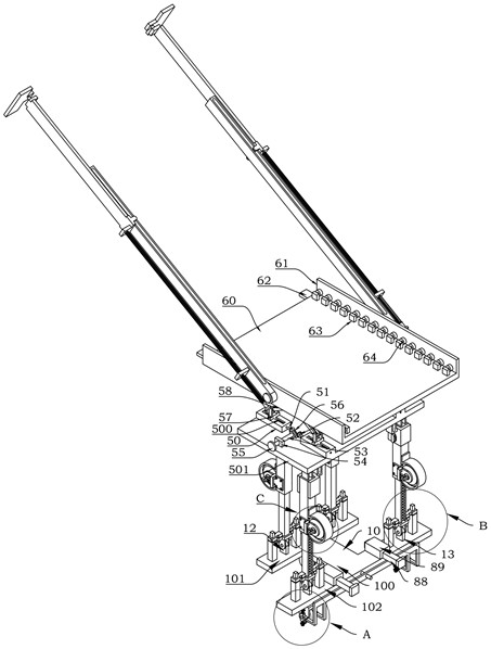
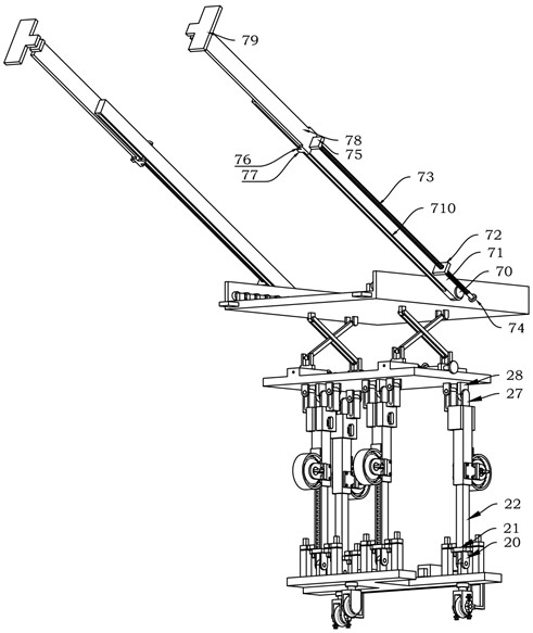
The invention discloses a modular electric control cabinet assembly vehicle, comprising: a sliding unit, a telescopic unit, a lifting unit, and a locking unit, which are used to lock the lower end of the telescopic unit so that the telescopic unit is perpendicular to the I-shaped bottom plate; the locking unit , used to lock the upper end of the telescopic unit, so that the telescopic unit is perpendicular to the upper plate; the placing table, used to place the assembly module of the electric control cabinet; the pulling unit, used to lock the position between the electric control cabinet and the assembly vehicle; slide The locking unit is used to lock the slide assembly; the telescopic unit is used for coarse adjustment of the height of the placing table, and the lifting unit is used for fine adjustment of the height of the placing table. It can carry out short-distance transportation of high and low voltage control modules, and can be used as an assembly platform for the assembly of high and low voltage control modules, which is convenient for transportation and assembly of high and low voltage control modules. The assembly efficiency of the electric control cabinet is improved, the assembly operation of electric control cabinets of different heights can be adapted, and the scope of use is expanded.

Description

technical field [0001] The invention relates to the related technical field of electrical control cabinet assembly equipment, in particular to a modular electric control cabinet assembly vehicle. Background technique [0002] The electrical control cabinet is composed of a high and low voltage control module, a box body and various corresponding functional components. The high and low voltage control module is generally an integral structure, and it is the heaviest Carrying the high and low voltage control modules during the process will increase the difficulty of protecting the high and low voltage control modules, and at the same time it is inconvenient to carry the electrical control cabinet. Therefore, the existing method is to assemble the high and low voltage control modules into the electric control cabinet through on-site assembly. This method greatly reduces the difficulty of the overall transportation of the electric control cabinet. [0003] The existing assembly...

Claims


Application Information

Patent Timeline
Patent Type & Authority Patents(China)
IPC IPC(8): H02B3/00
CPCH02B3/00
Inventor 韩文兵杨开勇
Owner CHINA NUCLEAR ELECTRICAL CO LTD
Why Eureka
Try Eureka