
Device for measuring coaxiality deviation of rotary transformer stator and rotor

A technology of resolver stator and coaxiality, applied in measuring devices, optical devices, instruments, etc., can solve the problems of inability to directly measure the coaxiality of the air gap, imprecise, and inability to accurately infer the air gap between the stator and the rotor. , to avoid errors or inability to measure, have good applicability, and improve measurement efficiency

Active Publication Date: 2020-06-19
湖南米艾西测控技术有限公司
View PDF21 Cites 5 Cited by
  • Summary
  • Abstract
  • Description
  • Claims
  • Application Information

AI Technical Summary

Problems solved by technology

[0003] Since the size of the air gap between the stator and the rotor is only a few tenths of a millimeter, the coaxiality of the air gap cannot be directly measured due to the limitation of the measuring tools. Therefore, the existing measurement methods basically measure the outer edge of the resolver stator and the rotor axis. concentricity deviation of the heart
Since the stator and rotor of the resolver have machining deviations, the coaxiality value measured by this measurement method is not the actual coaxiality value of the stator and rotor, but includes the processing eccentricity error value of the resolver stator and rotor, and also It is impossible to accurately deduce the actual air gap between the stator and the rotor, so from the measurement principle, this is very imprecise

Method used


Image

  • Device for measuring coaxiality deviation of rotary transformer stator and rotor
  • Device for measuring coaxiality deviation of rotary transformer stator and rotor
  • Device for measuring coaxiality deviation of rotary transformer stator and rotor

Examples


Embodiment Construction

[0021] In order to make the purpose, technical solution and advantages of the present invention clearer, the technical solution of the present invention will be described in detail below. Apparently, the described embodiments are only some of the embodiments of the present invention, but not all of them. Based on the embodiments of the present invention, all other implementations obtained by persons of ordinary skill in the art without making creative efforts fall within the protection scope of the present invention.

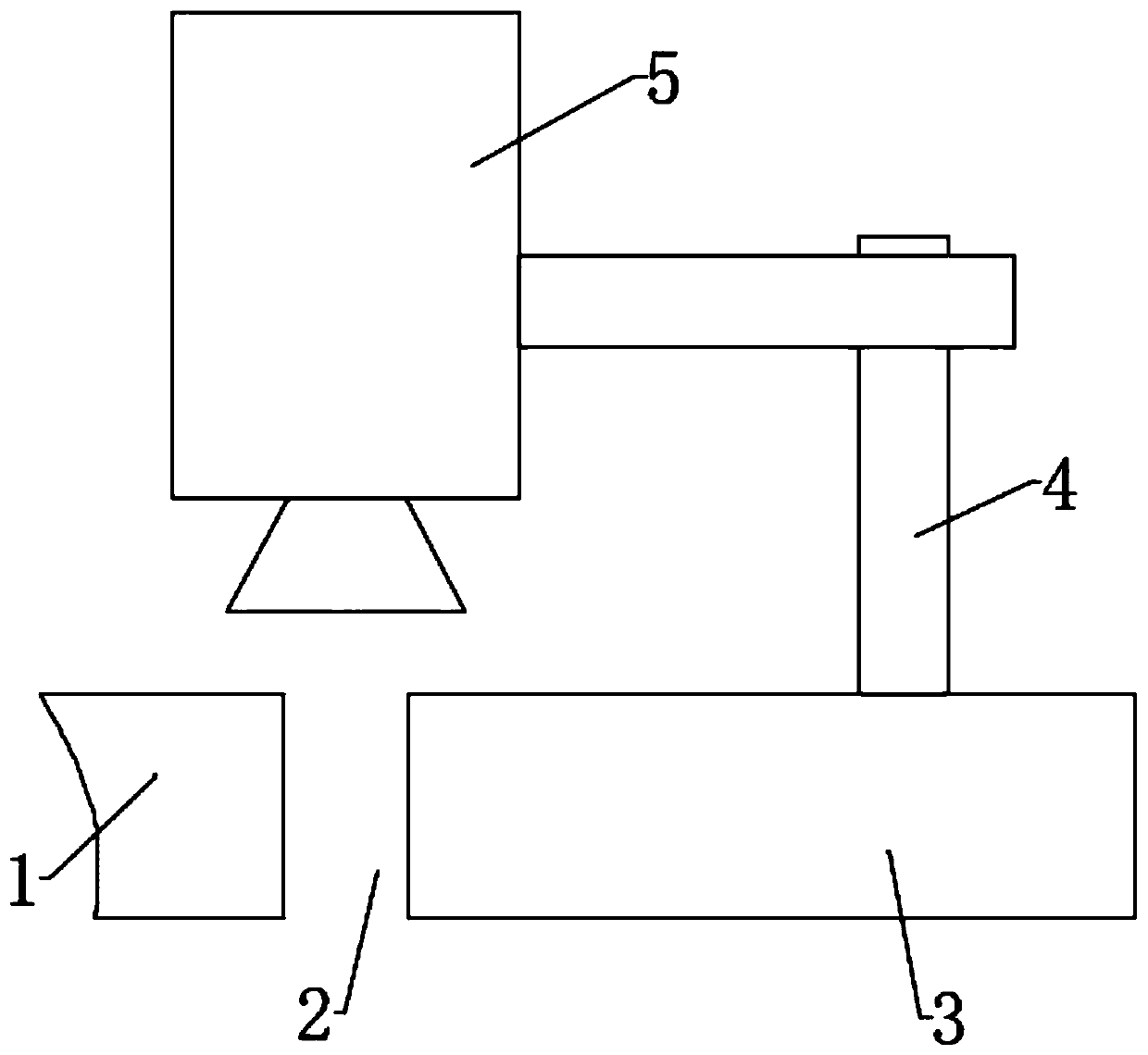
[0022] see figure 1 As shown, the present invention provides a device for measuring the coaxiality deviation between the resolver stator and the rotor, including a resolver stator bracket 1 for installing the resolver stator, a resolver rotor bracket 3 for installing the resolver rotor, and a scanning camera 5. The variable rotor bracket 3 is relatively fixed with the resolver rotor and can rotate synchronously. The scanning camera 5 is installed on the top of ...


PUM


Abstract

The invention discloses a device for measuring coaxiality deviation of a rotary transformer stator and a rotor. The device comprises a resolver stator support for installing a rotary transformer stator, a resolver rotor support for installing a rotary transformer rotor and a scanning camera, the rotary transformer rotor support and a rotary transformer rotor are relatively fixed and can rotate synchronously, the scanning camera is installed at the top of the rotary transformer rotor support through a camera support, and a camera body of the scanning camera vertically faces an air gap between the rotary transformer rotor and the rotary transformer stator. The device has the beneficial effects that by adopting a non-contact measurement scheme, the measurement efficiency is improved, and themeasurement error caused by the uneven surface of a workpiece in the traditional contact measurement method is solved; the width of the air gap between the inner edge of the stator and the outer edgeof the rotary transformer rotor is directly measured through the scanning camera, and the obtained coaxiality deviation value is higher in precision and better in applicability compared with a traditional indirect measurement method for measuring the axis of the stator and the axis of the rotor.

Description

technical field [0001] The invention relates to the technical field of automatic detection, in particular to a device for measuring the coaxiality deviation between a resolver stator and a rotor. Background technique [0002] The resolver is composed of two parts, the stator and the rotor. The deviation of the coaxiality between the two parts will cause the air gap between the resolver stator and the rotor to be uneven, which will have a great impact on the test accuracy. Therefore, in order to improve the installation accuracy of the resolver, it is necessary to put forward higher requirements on the air gap uniformity of the resolver stator and rotor. [0003] Since the size of the air gap between the stator and the rotor is only a few tenths of a millimeter, the coaxiality of the air gap cannot be directly measured due to the limitation of the measuring tools. Therefore, the existing measurement methods basically measure the outer edge of the resolver stator and the rotor...

Claims


Application Information

Patent Timeline
Patent Type & Authority Applications(China)
IPC IPC(8): G01B11/27G01B11/02G01B11/14
CPCG01B11/27G01B11/022G01B11/14
Inventor 陈乐舒王勇
Owner 湖南米艾西测控技术有限公司
Learn More