
Parallelism measuring device and method

A technology of measuring device and measuring method, applied in the direction of angle/taper measurement, etc., can solve the problems of affecting accuracy, time-consuming and precise measurement of parallelism, etc.

Pending Publication Date: 2020-06-19
HIMAX TECH LTD
View PDF10 Cites 2 Cited by
  • Summary
  • Abstract
  • Description
  • Claims
  • Application Information

AI Technical Summary

Problems solved by technology

Generally speaking, after the wafer imprinting is completed, the operator needs to check the imprinted product to confirm the parallelism between the lower imprinting surface and the upper imprinting surface of the imprinting machine. However, this method is not only time-consuming, but also It results in high cost, and it is impossible to accurately measure the parallelism during imprinting through numerical quantification, so it will affect the accuracy of parallelism correction

Method used


Image

  • Parallelism measuring device and method
  • Parallelism measuring device and method
  • Parallelism measuring device and method

Examples


Embodiment Construction

[0034] Embodiments of the invention are discussed in detail below. It should be appreciated, however, that the embodiments provide many applicable concepts that can be implemented in a wide variety of specific contexts. The discussed and disclosed embodiments are for illustration only and are not intended to limit the scope of the present invention.

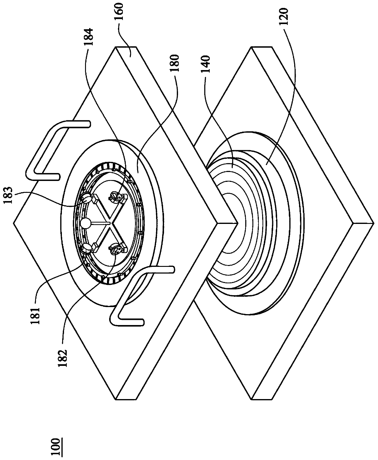
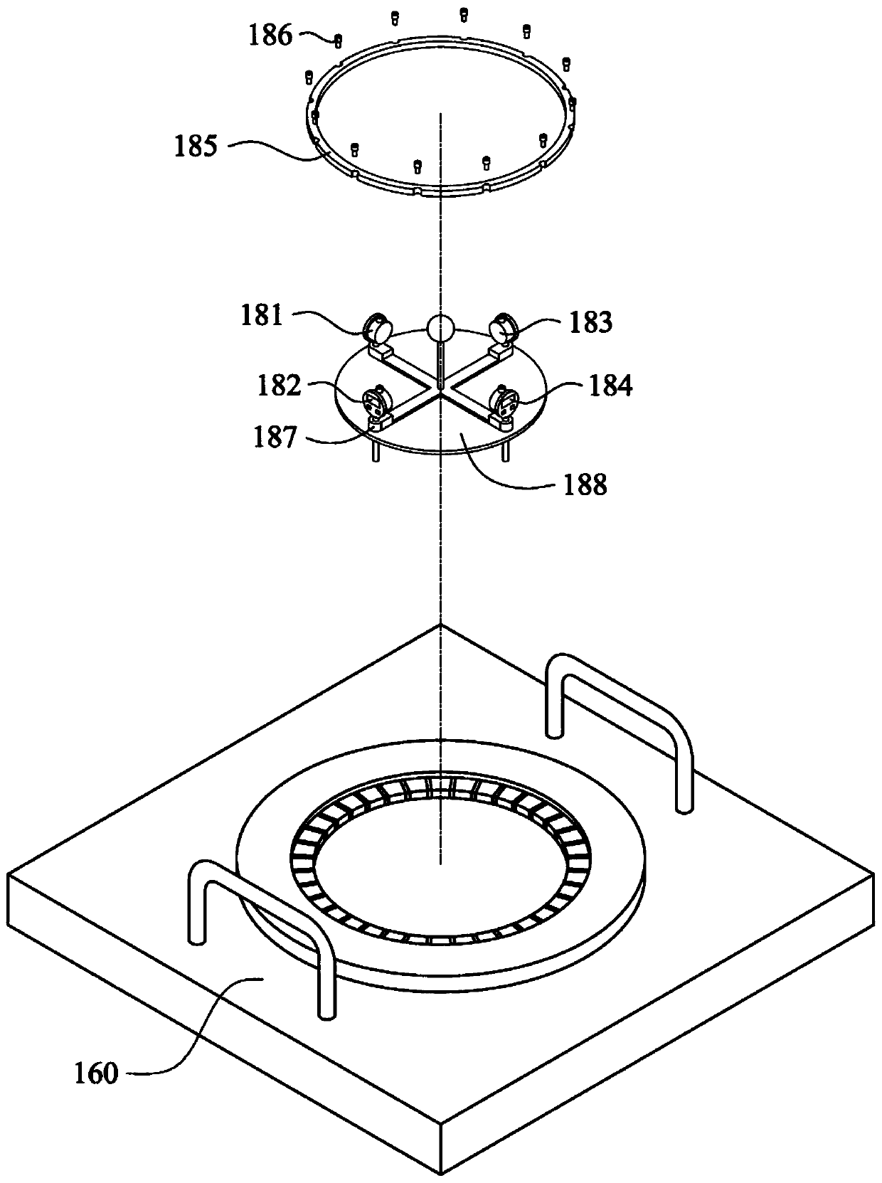
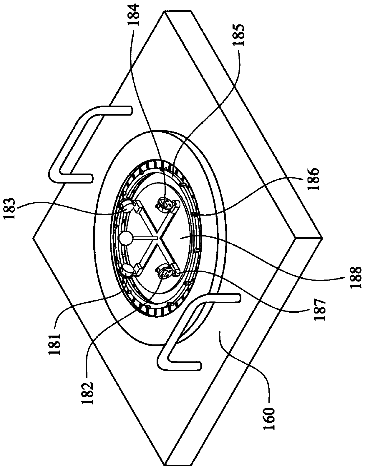
[0035] figure 1 A schematic configuration diagram of the parallelism measuring device 100 according to an embodiment of the present disclosure. The parallelism measuring device 100 is used to measure the parallelism during embossing. The parallelism measuring device 100 includes a lower embossing surface mechanism 120 , a calibration quartz plate 140 , a clamping seat 160 and a parallelism measuring jig 180 . The calibration quartz plate 140 is adsorbed on the lower stamping surface mechanism 120 . In the embodiment of the present disclosure, the calibration quartz plate 140 is pasted on the lower imprinting surface mechanism ...


PUM


Abstract

The invention discloses a parallelism measuring device for measuring parallelism during imprinting. The parallelism measuring device comprises a lower imprinting surface mechanism, a correction quartzplate, a clamping seat and a parallelism measuring jig, and the correction quartz plate is adsorbed on the lower impressing surface mechanism. The clamping seat is arranged above the correction quartz plate. The parallelism measuring jig is installed and fixed on the clamping seat. The parallelism measuring jig comprises a plurality of dial indicators used for measuring parallelism during imprinting.

Description

technical field [0001] Embodiments of the present disclosure relate to a parallelism measuring device, in particular to a parallelism measuring device and a method thereof for measuring parallelism during imprinting. Background technique [0002] In the wafer manufacturing process, the wafer is imprinted by an embossing machine, so the parallelism between the lower embossing surface and the upper embossing surface of the embossing machine will directly affect the yield of the finished product. Generally speaking, after the wafer imprinting is completed, the operator needs to check the imprinted product to confirm the parallelism between the lower imprinting surface and the upper imprinting surface of the imprinting machine. However, this method is not only time-consuming, but also This results in high costs, and it is impossible to accurately measure the parallelism during embossing through numerical quantification, which will affect the accuracy of parallelism correction. ...

Claims


Application Information

Patent Timeline
IPC IPC(8): G01B5/24
CPCG01B5/24
Inventor 张瑞堂
Owner HIMAX TECH LTD
Learn More