
Self-adaptive friction energy consuming and vibration reducing device for bridge beam structure

A friction energy dissipation and vibration damping device technology, applied in bridges, bridge parts, bridge construction, etc., can solve the problems of inability to control bridge vibration energy dissipation, poor vibration reduction effect, etc., achieve good energy consumption and vibration reduction, prevent mutual Effects of collisions and falling beams

Active Publication Date: 2020-06-19
武汉理工大设计研究院有限公司
View PDF6 Cites 1 Cited by
  • Summary
  • Abstract
  • Description
  • Claims
  • Application Information

AI Technical Summary

Problems solved by technology

[0005] In view of this, the present invention provides a bridge structure self-adaptive frictional energy dissipation vibration damping device to solve the problem mentioned above that when the vibration displacement of the bridge structure is not large, the vibration energy consumption of the bridge cannot be adjusted and the vibration damping effect is not good. The problem

Method used


Image

  • Self-adaptive friction energy consuming and vibration reducing device for bridge beam structure
  • Self-adaptive friction energy consuming and vibration reducing device for bridge beam structure
  • Self-adaptive friction energy consuming and vibration reducing device for bridge beam structure

Examples


Embodiment Construction

[0023] The principles and features of the present invention are described below in conjunction with the accompanying drawings, and the examples given are only used to explain the present invention, and are not intended to limit the scope of the present invention. In the following paragraphs the invention is described more specifically by way of example with reference to the accompanying drawings. Advantages and features of the present invention will be apparent from the following description and claims. It should be noted that all the drawings are in a very simplified form and use imprecise scales, and are only used to facilitate and clearly assist the purpose of illustrating the embodiments of the present invention.

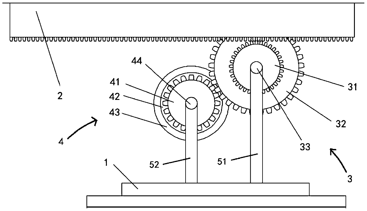
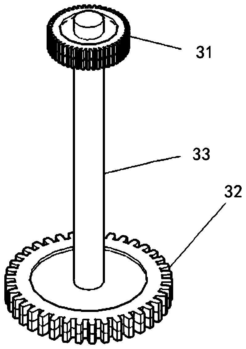
[0024] Such as Figure 1-2 as shown, figure 1 It is a structural schematic diagram of an embodiment of a bridge structure self-adaptive friction energy dissipation and vibration reduction device provided by the present invention; figure 2 It is a structural ...


PUM


Abstract

The invention discloses a self-adaptive friction energy consuming and vibration reducing device for a bridge beam structure. The self-adaptive friction energy consuming and vibration reducing device comprises a base, a displacement conversion rack, a displacement amplifying assembly and a friction energy consuming assembly. The displacement conversion rack is fixedly installed on the end portion of a bridge beam. The displacement conversion rack moves horizontally along with horizontal vibration of the bridge beam. The displacement amplifying assembly and the friction energy consuming assemblyare fixedly installed on the base. One end of the displacement amplifying assembly is in transmission connection with the displacement conversion rack, and thus the horizontal vibration of the bridgebeam is converted into rotating motion of the displacement amplifying assembly. The other end of the displacement amplifying assembly is in transmission connection with the friction energy consumingassembly, and thus while displacement of the horizontal vibration of the bridge beam is amplified indirectly, the rotating motion of the displacement amplifying assembly is conveyed to the friction energy consuming assembly. By means of friction energy consuming, braking of the rotating motion of the friction energy consuming assembly can be achieved, effective braking is obtained under heat energy consumption and dissipation generated by friction, and energy consuming and vibration reducing of the bridge beam are good.

Description

technical field [0001] The invention relates to the technical field of structural vibration control, in particular to a bridge structure self-adaptive frictional energy dissipation vibration damping device. Background technique [0002] Bridge structure vibration is an important factor causing bridge damage. Due to the large span of the bridge structure and the requirements of its use function, it is often affected by vibration caused by earthquakes, vibrations caused by loads, and even vibrations caused by vehicle-bridge coupling. [0003] However, most of the existing countermeasures are: to improve the vibration response of the bridge by enhancing the structural strength design, but this kind of cost is high and the economy is poor; to actively control the vibration of the bridge structure through energy consumption and vibration reduction, specifically, its Under the action of the damper, the energy input into the bridge is dissipated, so as to achieve the purpose of sup...

Claims


Application Information

Patent Timeline
IPC IPC(8): F16F15/02F16H37/12E01D19/00
CPCE01D19/00F16F15/02F16H37/124
Inventor 徐训刘志昂陈浩朱亚杉田克兢徐瑞红林廷灿
Owner 武汉理工大设计研究院有限公司
Learn More