Bead conveying device for accessory processing and bead stringing
A conveying device and bead technology, which is applied to conveyor objects, transportation and packaging, etc., can solve the problems of low work efficiency, unstable wire holding, trouble, etc., and achieve the effect of improving efficiency and convenient operation.
- Summary
- Abstract
- Description
- Claims
- Application Information
AI Technical Summary
Problems solved by technology
Method used
Image
Examples
Embodiment 1
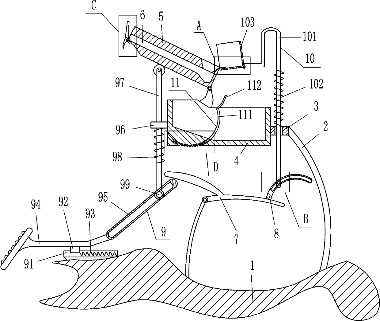
[0021] see Figure 1-Figure 4 , the application provides a bead conveying device for jewelry processing beads, including a base 1, a pole 2, a first guide sleeve 3, a placement frame 4, a cylinder 5, a movable baffle 51, a first torsion spring 52, a special-shaped Rod 7, arc-shaped orifice plate 8, swing mechanism 9 and feeding mechanism 10, support rod 2 is fixedly connected to the top right side of base 1, first guide sleeve 3 is fixedly connected to the top of support rod 2, and first guide sleeve 3 The left side is fixed with a placement frame 4 for placing beads. The left side of the inner bottom of the placement frame 4 is an inclined plane. A cylinder 5 is hinged between the top and left side of the placement frame 4. The middle part of the cylinder 5 is horizontally opened to allow beads to be discharged. The discharge port 6 of the cylinder 5 is hinged with a movable baffle 51 that can limit the beads, and the hinge of the movable baffle 51 and the cylinder 5 is provi...
Embodiment 2
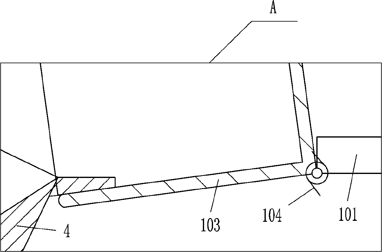
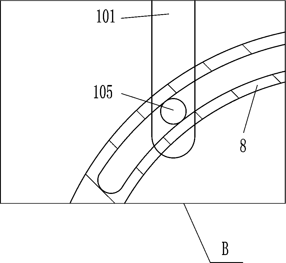
[0026] On the basis of Example 1, please refer to figure 1 , figure 2 and image 3 , the feeding mechanism 10 includes an n-type rod 101, a third spring 102, a movable frame 103, a second torsion spring 104 and a second fixed shaft 105, and the sliding type in the first guide sleeve 3 is provided with an n-type rod 101, n The lower part of the front side of the type bar 101 is fixedly connected with the second fixed shaft 105, and the second fixed shaft 105 is located in the arc-shaped orifice plate 8 to cooperate with it. Three springs 102, the left end of the n-type bar 101 is hinged with a movable frame 103 that can move the beads, the hinge of the movable frame 103 and the n-type bar 101 is provided with a second torsion spring 104, and the left part of the movable frame 103 is in contact with the cylinder 5. Tilt setting.
[0027] When the operator steps on the pedal 94 to move to the right, the arc-shaped orifice plate 8 swings downward to drive the second fixed shaf...
Embodiment 3
[0029] On the basis of Embodiment 1 and Embodiment 2, please refer to figure 1 and Figure 4 , also includes a stopper mechanism 11 that can block the beads. The stopper mechanism 11 includes an arc-shaped baffle plate 111, a contact plate 112 and a fourth spring 114. The lower side of the left part of the placement frame 4 has an arc-shaped groove 113. The arc-shaped Sliding in the groove 113 is provided with an arc-shaped baffle 111 that can block the beads. A fourth spring 114 is wound between the lower part of the arc-shaped baffle 111 and the left part of the arc-shaped groove 113, and a contact plate that cooperates with the movable frame 103 112 is installed on the top of the arc-shaped baffle 111, and the contact plate 112 is inclined.
[0030] When the operator pours an appropriate amount of beads into the placement frame 4, the arc-shaped baffle plate 111 blocks the beads, and then when the movable frame 103 moves downward, the movable frame 103 contacts the contact...
PUM
 Abstract
Description
Claims
Application Information
 - R&D
- Intellectual Property
- Life Sciences
- Materials
- Tech Scout
- Unparalleled Data Quality
- Higher Quality Content
- 60% Fewer Hallucinations
Browse by: Latest US Patents, China's latest patents, Technical Efficacy Thesaurus, Application Domain, Technology Topic, Popular Technical Reports.
© 2025 PatSnap. All rights reserved.Legal|Privacy policy|Modern Slavery Act Transparency Statement|Sitemap|About US| Contact US: help@patsnap.com


