
Industrial robot six-dimension rigidity error compensation system and compensation method thereof

An industrial robot and error compensation technology, applied in the field of robots, can solve the problems of low identification accuracy of industrial robot stiffness parameters, affecting the accuracy performance of industrial robots, and measurement data unable to fully reflect changes in industrial robot stiffness.

Active Publication Date: 2020-06-19
NANJING INST OF TECH
View PDF14 Cites 2 Cited by
  • Summary
  • Abstract
  • Description
  • Claims
  • Application Information

AI Technical Summary

Problems solved by technology

At present, the joint stiffness model of industrial robots mainly considers the stiffness parameters of the joint rotation axis, while ignoring the stiffness parameters of other dimensions. When the end load of the robot is large, it may still cause a large positioning error, and there is no compensation for six-dimensional stiffness errors. method
At present, the static load method of the robot is mainly used to identify the stiffness parameters of the industrial robot, but the load application system is usually relatively complicated, and even the working space of the robot is limited, and the data measurement of a large working space cannot be realized, and the measurement data cannot fully reflect the stiffness change of the industrial robot. This will lead to low identification accuracy of industrial robot stiffness parameters, which will directly affect the precision performance of industrial robots

Method used


Image

  • Industrial robot six-dimension rigidity error compensation system and compensation method thereof
  • Industrial robot six-dimension rigidity error compensation system and compensation method thereof
  • Industrial robot six-dimension rigidity error compensation system and compensation method thereof

Examples


Embodiment Construction

[0039] The specific implementation manners of the present invention will be described below in conjunction with the accompanying drawings.

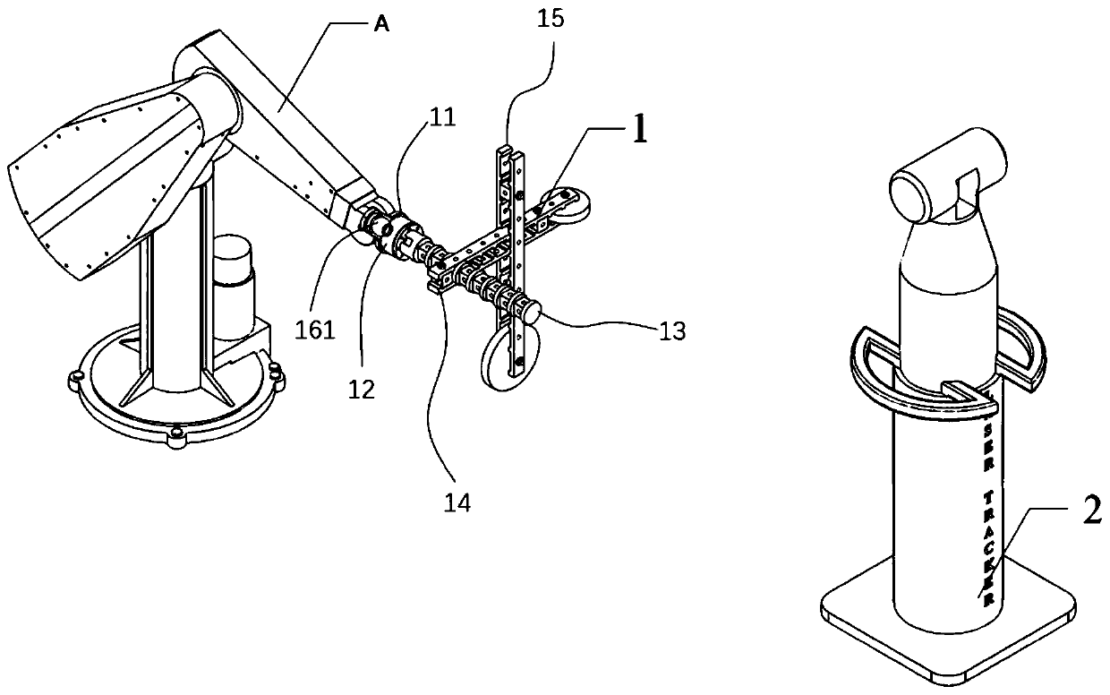
[0040] Such as figure 1 As shown, the present invention provides a six-dimensional stiffness error compensation system for an industrial robot, including a load measuring device 1 and a laser tracker 2 .

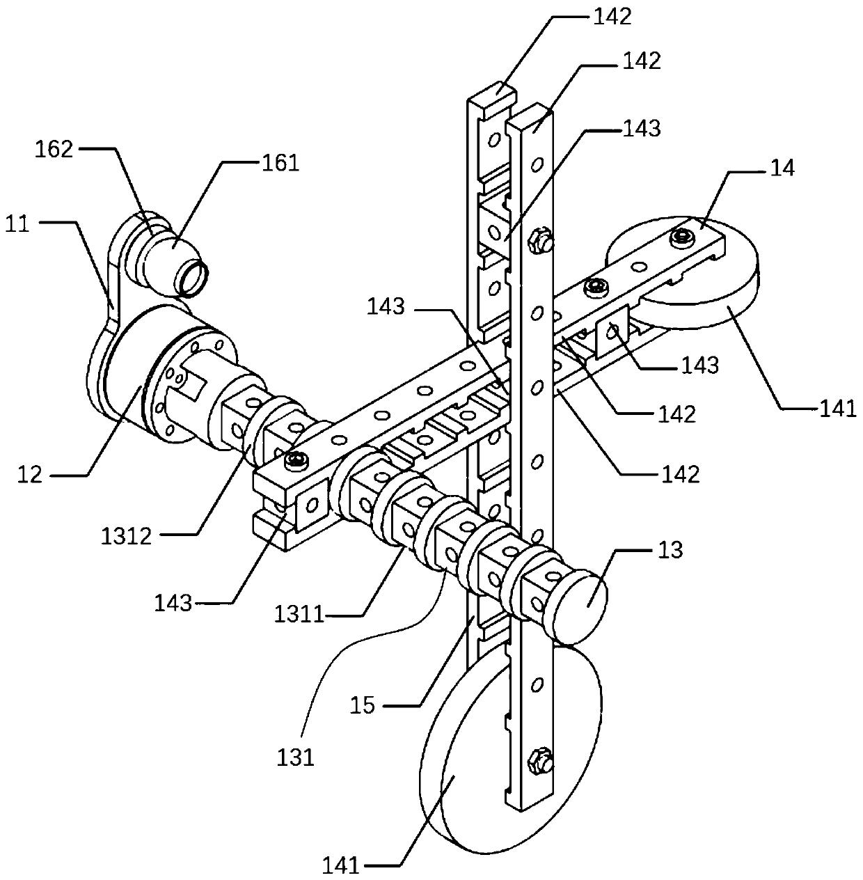
[0041] The load measuring device 1 is fixed on the end of the industrial robot A, including an adapter plate 11, a six-dimensional force sensor 12, an X-axis loading device 13, a Y-axis loading device 14, a Z-axis loading device 15, a target ball 161 and a magnetic target ball base Seat 162.

[0042] The adapter plate 11 is fixedly connected with the end flange of the industrial robot A.

[0043] The six-dimensional force sensor 12 is fixed on the adapter plate 11 . The six-dimensional force sensor 12 is installed concentrically with the end flange of the industrial robot A through the adapter plate 11 .

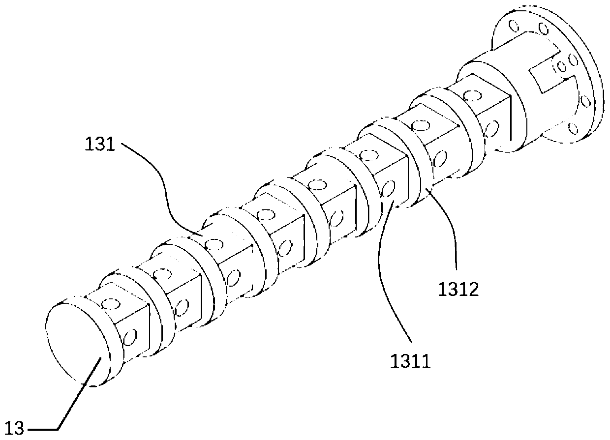
[0044] The X-axis loading ...


PUM


Abstract

The invention discloses an industrial robot six-dimension rigidity error compensation system and compensation method thereof. The system comprises a load measuring device and a laser tracker. The loadmeasuring device is fixed to the tail end of an industrial robot and comprises an adapter plate, a six-dimension force sensor, an X-axis loading device, a Y-axis loading device, a Z-axis loading device and a target ball. The adapter plate is fixedly connected with a tail end flange disc of the industrial robot. The six-dimension force sensor is fixed to the adapter plate. The front end of the X-axis loading device is fixed to the six-dimension force sensor. The Y-axis loading device is arranged on the X-axis loading device. The Z-axis loading device is arranged on the Y-axis loading device. The Y-axis loading device and the Z-axis loading device are provided with weights correspondingly. The weights can be arranged at any position in the length directions of the Y-axis loading device andthe Z-axis loading device. The target ball is fixedly arranged on the adapter plate. The laser tracker is located on the rear side of the industrial robot. The space position of the target ball can bemeasured. The system has the advantages of being simple in structure and capable of effectively improving the locating precision.

Description

technical field [0001] The invention belongs to the field of robots, and relates to an industrial robot parameter calibration technology, in particular to a six-dimensional stiffness error compensation system and a compensation method of an industrial robot based on variable kinematic parameters. Background technique [0002] With the rapid development of robot technology, industrial robots are gradually expanding to high-end manufacturing fields, such as hole making / riveting in the aerospace industry, wind turbine blade grinding, etc. And these application fields have higher and higher precision requirements for industrial robots. Studies have shown that the absolute positioning error of industrial robots is mainly divided into geometric parameter error and non-geometric parameter error, of which geometric parameter error accounts for more than 80% of the total error. This type of error can be compensated with high precision through geometric parameter calibration technolog...

Claims


Application Information

Patent Timeline
IPC IPC(8): B25J9/16
CPCB25J9/1638
Inventor 乔贵方张颖吕仲艳孙大林万其温秀兰
Owner NANJING INST OF TECH
Learn More