
Fuel supply device for cryogenic fuels, and method for operating a fuel supply device for cryogenic fuels

A low-temperature fuel and fuel delivery technology, which is applied to pump devices, oil supply devices, charging systems, etc., can solve the problems of large size of the pre-delivery pump and the influence of the efficiency of the fuel delivery device, and achieve the effect of reducing the installation space requirement.

Active Publication Date: 2020-06-09
ROBERT BOSCH GMBH
View PDF7 Cites 0 Cited by
  • Summary
  • Abstract
  • Description
  • Claims
  • Application Information

AI Technical Summary

Problems solved by technology

This means that the prefeed pump is often overdimensioned, which has a negative effect on the efficiency of the fuel delivery device

Method used


Image

  • Fuel supply device for cryogenic fuels, and method for operating a fuel supply device for cryogenic fuels
  • Fuel supply device for cryogenic fuels, and method for operating a fuel supply device for cryogenic fuels
  • Fuel supply device for cryogenic fuels, and method for operating a fuel supply device for cryogenic fuels

Examples


Embodiment Construction

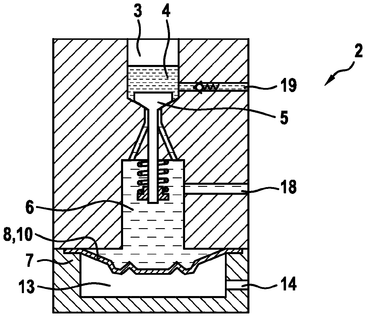
[0024] exist figure 1 The fuel delivery device according to the invention shown in , comprises a pre-feed pump 1 and a high-pressure pump 2 , wherein the pre-feed pump 1 is currently arranged in the bottom region of a tank 15 for storing cryogenic fuel. A liquid phase 16 of the fuel is present there, which is covered by a gaseous phase 17 of the fuel. The arrangement of the pre-feed pump 1 in the tank 15 has the advantage that the structural outlay for connecting the pre-feed pump 1 to the high-pressure pump 2 is reduced since only the low-pressure line 18 needs to be led out of the tank 15 . The prefeed pump 1 can in particular be embodied as a side channel pump or a centrifugal pump.

[0025] The additionally provided high-pressure pump 2 is designed as a single-piston pump. The single-piston pump has a compression chamber 4 which is delimited by a reciprocating piston 3 and which can be filled with cryogenic fuel via a suction valve 5 . In this case, fuel is withdrawn fr...


PUM


Abstract

The invention relates to a fuel supply device for cryogenic fuels, said device comprising a pre-supply pump (1) and a high-pressure pump (2), wherein the high-pressure pump (2) has a reciprocally movable piston (3) which delimits a compression chamber (4). According to the invention, the compression chamber (4) can be connected via a suction valve (5) to a low-pressure accumulator volume (6) whichcan be filled with cryogenic fuel via the pre-supply pump (1). The invention also relates to a method for operating a fuel supply device for cryogenic fuels.

Description

technical field [0001] The invention relates to a fuel delivery device for cryogenic fuels having the features of the preamble of claim 1 . The invention also relates to a method for operating a fuel delivery device for cryogenic fuels with the features of the preamble of claim 8 . [0002] The cryogenic fuel may in particular be natural gas (“Natural Gas”=NG), which is stored in liquid form (“Liquefied Natural Gas”=LNG: liquefied natural gas) in motor vehicles for operating the internal combustion engine in specially designed tanks for this purpose. Background technique [0003] The low-temperature fuel, such as natural gas, is compressed by means of a high-pressure pump before being blown into the combustion chamber of the internal combustion engine. The high-pressure pump can be designed as a piston pump, in particular as a single-piston pump that is unbalanced in volume, so that undesired volume fluctuations or pressure fluctuations can occur, especially in the low-pres...

Claims


Application Information

Patent Timeline
Patent Type & Authority Applications(China)
IPC IPC(8): F02M21/02F04B11/00F04B9/08
CPCF04B9/08F04B11/0008F02M21/0215F02M21/0221F02M21/0239F02M21/0245F04B19/24F04B23/103F04B23/02F04B2015/081F04B15/08F04B11/0033Y02T10/30F04B23/14
Inventor D·施尼特格A·贝特M·菲尔挨克
Owner ROBERT BOSCH GMBH
Learn More