
Laminating method and laminating device

A lamination device and lamination technology, applied in the direction of identification devices, instruments, etc., can solve the problems that affect the yield rate and display effect of curved screen products, complex design, difficult control, etc., to improve yield rate and display effect, and simple control The effect of streamlining, saving engineering and reducing costs

Active Publication Date: 2020-06-09
BOE TECH GRP CO LTD +1
View PDF21 Cites 7 Cited by
  • Summary
  • Abstract
  • Description
  • Claims
  • Application Information

AI Technical Summary

Problems solved by technology

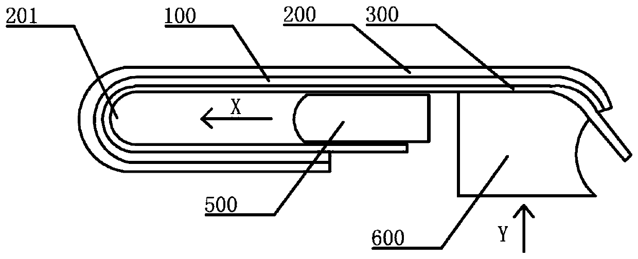
[0004] (1) if figure 1 As shown, the scroll wheel 400 is used to scroll along the surface of the flexible display panel 100 (in figure 1 In the example, the roller 400 rolls along the X direction) to compress the flexible display panel 100 and the cover plate 200, but because the inner space formed by the bending area 201 of the flexible display panel 100 is narrow, thus The diameter of the restricting roller 400 is small, resulting in insufficient pressure on the roller 400, which may cause local compaction failure;
[0005] (2) if figure 2 As shown, the lamination is carried out by using a profiling jig, for example: using the slider 500 to slide on the surface of the flexible display panel 100 to compact the bending area 201 of the flexible display panel 100 (in the figure 2 In the example, the slider 500 slides along the X direction), and at the same time, the support block 600 matching the curved surface of the flexible display panel 100 is used to compact the non-bending area of ​​the flexible display panel (in figure 2 In the example shown above, the support block 600 compresses the flexible display panel 100 along the Y direction), but the design of the mechanism is complicated, and it is difficult to control during the bonding process, and the slider 500 is prone to cause flexibility during the sliding process. Problems such as cracks on the display screen 100 and air bubbles between the flexible display panel 100 and the cover plate 200 affect the product yield and display effect of the curved screen

Method used


Image

  • Laminating method and laminating device
  • Laminating method and laminating device
  • Laminating method and laminating device

Examples


Embodiment Construction

[0040] Exemplary embodiments of the present invention will now be described more fully with reference to the accompanying drawings. However, example embodiments may be embodied in many forms, and this invention should not be construed as limited to the embodiments set forth herein. On the contrary, providing these exemplary embodiments can make the present invention more comprehensive and complete, and facilitate the full transfer of the inventive concept to those skilled in the art. The same reference numerals denote the same or similar elements, components or parts in the drawings, and thus their repeated descriptions will be omitted.

[0041] On the premise of conforming to the technical concept of the present invention, the features, structures, characteristics or other details described in a specific embodiment do not exclude that they can be combined in one or more other embodiments in a suitable manner.

[0042] In the description of the specific embodiments, the featu...


PUM


Abstract

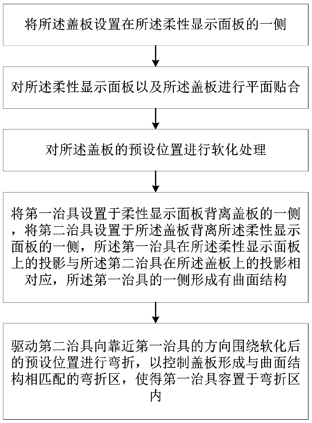
The invention discloses a laminating method, which is used for laminating a flexible display panel and a cover plate, and comprises the following steps of: arranging the cover plate on one side of theflexible display panel; carrying out plane fitting on the flexible display panel and the cover plate; softening the preset position of the cover plate; arranging a first jig on one side, deviating from the cover plate, of the flexible display panel, and arranging a second jig on the side, away from the flexible display panel, of the cover plate, wherein the projection of the first jig on the flexible display panel corresponds to the projection of the second jig on the cover plate, and a curved surface structure is formed on one side of the first jig; and driving the second jig to be bent around the softened preset position in the direction close to the first jig, so that the cover plate is controlled to form a bent area matched with the curved surface structure, and the first jig is contained in the bent area. According to the invention, the product yield and the display effect are improved.

Description

technical field [0001] The invention relates to the field of display technology. More specifically, it relates to a bonding method and a bonding device. Background technique [0002] With the development of science and technology, curved screens are becoming more and more popular. Curved screens generally include a cover and a flexible display panel that fits the cover. The cover can be a cover with both ends bent inward. plate, and the flexible display panel is attached to the inner side of the cover plate. [0003] In the related art, the flexible display panel and one side of the cover are pre-formed with a bending area. The bonding machine draws the gap between the flexible display panel and the cover to be hollow to realize the lamination of the flexible display panel and the cover. In the process of laminating the flexible display panel and the cover, the following two methods are generally used: : [0004] (1) if figure 1 As shown, the scroll wheel 400 is used to...

Claims


Application Information

Patent Timeline
IPC IPC(8): G09F9/30
CPCG09F9/301
Inventor 王家林曾飞范荣坤黄修雄林治冰梁海涛秦朝学
Owner BOE TECH GRP CO LTD
Learn More