
Truss rib laminated plate with height limiting devices, die table assembly and production process thereof

A production process and technology of laminated board, applied in the direction of mold auxiliary parts, floors, building components, etc., can solve problems such as extrusion deformation, laminated board damage, bottom plate cracking, etc., to achieve high strength, high precision, and reduce the height of the mold table. Effect

Pending Publication Date: 2020-06-05
赵红玲
View PDF0 Cites 0 Cited by
  • Summary
  • Abstract
  • Description
  • Claims
  • Application Information

AI Technical Summary

Problems solved by technology

[0013] The truss bars and stressed floor of the existing laminated slab structure are not fully protected, and are easily deformed and cracked during storage and transportation; during storage and transportation, either the bottom plate presses the truss bars or the bottom plate Either method of pressing the bottom plate will cause damage to the laminated plate, either the truss tendon is damaged or deformed, or the bottom plate is cracked
In short, there are hidden dangers in the production, storage, transportation and installation of existing laminated panels.

Method used


Image

  • Truss rib laminated plate with height limiting devices, die table assembly and production process thereof
  • Truss rib laminated plate with height limiting devices, die table assembly and production process thereof
  • Truss rib laminated plate with height limiting devices, die table assembly and production process thereof

Examples


Embodiment Construction

[0054] In order to make the object, technical solution and advantages of the present invention clearer, the present invention will be described in detail below in conjunction with the accompanying drawings and specific embodiments.

[0055] like figure 2As shown, the present invention provides a truss bar laminated slab with a height limiting device, which includes a prefabricated base plate 1 and a cast-in-place layer. The truss bars 7 are located on the same side, and the height of each height limiting device exposed outside the prefabricated floor 1 is equal to the thickness of the cast-in-place layer.

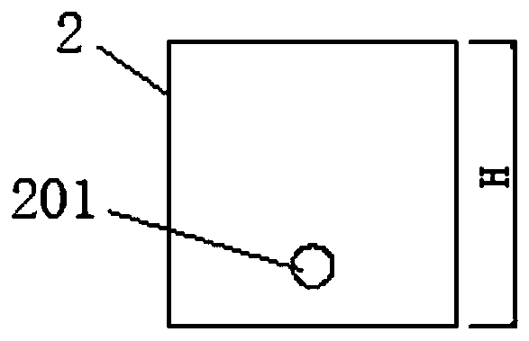
[0056] In the embodiment of the present invention, the height-limiting device includes a height-limiting pier 2, and the height-limiting pier 2 and the prefabricated floor 1 are poured into an integrated structure.

[0057] Further, the height-limiting pier 2 is provided with a fixed engagement structure with the prefabricated floor 1 during pouring.

[0058] In the embo...


PUM


Abstract

The invention belongs to the technical field of fabricated buildings, and particularly relates to a truss rib laminated plate with height limiting devices, a die table assembly and a production process thereof. The truss rib laminated plate with the height limiting devices comprises a prefabricated bottom plate and a cast-in-place layer. A plurality of height limiting devices are embedded in the prefabricated bottom plate. The height limiting devices and truss ribs on the prefabricated bottom plate are located on the same side. The height of each height limiting device exposed outside the prefabricated bottom plate is equal to the thickness of the cast-in-place layer. Each height limiting device comprises a height limiting pier, and the height limiting piers and the prefabricated bottom plate are poured to from an integral structure. According to the truss rib laminated plate, the height limiting piers and the prefabricated bottom plate are poured together, so that a slab thickness control point can be accurately determined; cast-in-place layer concrete is flush with the height limiting piers, and design requirements are met; and in addition, on storage and transportation stackingfulcrums, the precision is high, the strength is high, force is transmitted up and down, and neither the truss ribs nor a bottom plate body is damaged.

Description

technical field [0001] The invention belongs to the technical field of prefabricated buildings, and in particular relates to a truss bar laminated plate with a height limiting device, a mold platform assembly and a production process thereof. Background technique [0002] Laminated slab is a commonly used component form in the field of prefabricated construction engineering. It refers to that the reinforced concrete components are prefabricated in a factory in one step, and the other part is cast-in-place and laminated at the construction site to form a laminated slab. The laminated slab includes the bottom slab and the cast-in-place layer. The bottom slab is also used as a permanent formwork during construction and is also a part of the stressed structural member. The laminated slab generally refers to the prefabricated bottom slab. The basic requirements for the superposition of the prefabricated floor and cast-in-place concrete are that the contact surface should firstly ...

Claims


Application Information

Patent Timeline
Patent Type & Authority Applications(China)
IPC IPC(8): E04B5/17B28B7/00B28B1/29B28B11/08
CPCB28B1/29B28B7/0002B28B7/0032B28B11/0818E04B5/17
Inventor 郑永春
Owner 赵红玲
Learn More