A high-speed braiding machine spindle installation track structure

A high-speed knitting machine and spindle technology, which is applied in the direction of knitting, textiles, and papermaking, can solve the problems of sliding seat hitting the mounting seat and high risk of use, and achieves reduced downtime due to failure, high production efficiency, and reasonable structure. Effect

Active Publication Date: 2021-05-07
HANGZHOU POLYTECHNIC
View PDF9 Cites 0 Cited by
  • Summary
  • Abstract
  • Description
  • Claims
  • Application Information

AI Technical Summary

Problems solved by technology

[0002] The spindle is one of the important components of the braiding machine. The quality of the spindle determines the weaving quality of the braiding machine. It not only enables the wire strands to be automatically retracted, but also allows the wire strands to maintain their tension, so that they are firmly attached to the pipe. The current market There are various types of knitting machines on the market, and their structures and functions are quite different. In the prior art, there are knitting machines that can adjust the position of the spindle through the installation track. Drive the screw to rotate, and the screw rotates to drive the sliding seat that matches the screw to move. The spindle is installed on the sliding seat to achieve the purpose of adjusting the position of the spindle. When the motor is rotating, the screw is always moving. If it is not timely stop, it may cause accidents where the sliding seat hits the mounting seat, and the use is more dangerous

Method used


Image

  • A high-speed braiding machine spindle installation track structure
  • A high-speed braiding machine spindle installation track structure
  • A high-speed braiding machine spindle installation track structure

Examples


Embodiment Construction

[0031] The following will clearly and completely describe the technical solutions in the embodiments of the present invention with reference to the accompanying drawings in the embodiments of the present invention. Obviously, the described embodiments are only some, not all, embodiments of the present invention. Based on the embodiments of the present invention, all other embodiments obtained by persons of ordinary skill in the art without making creative efforts belong to the protection scope of the present invention.

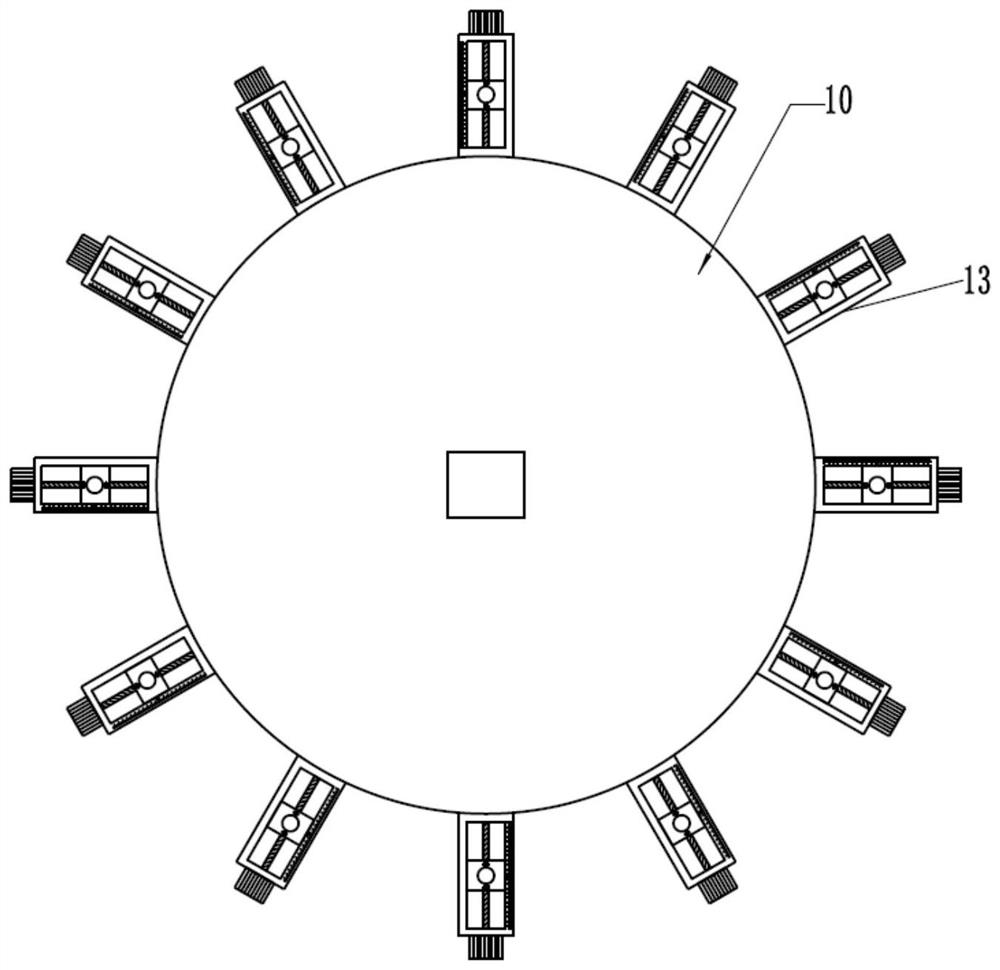
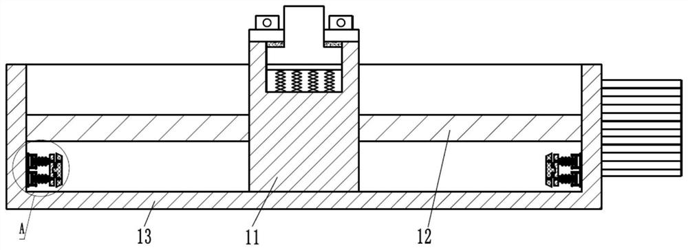
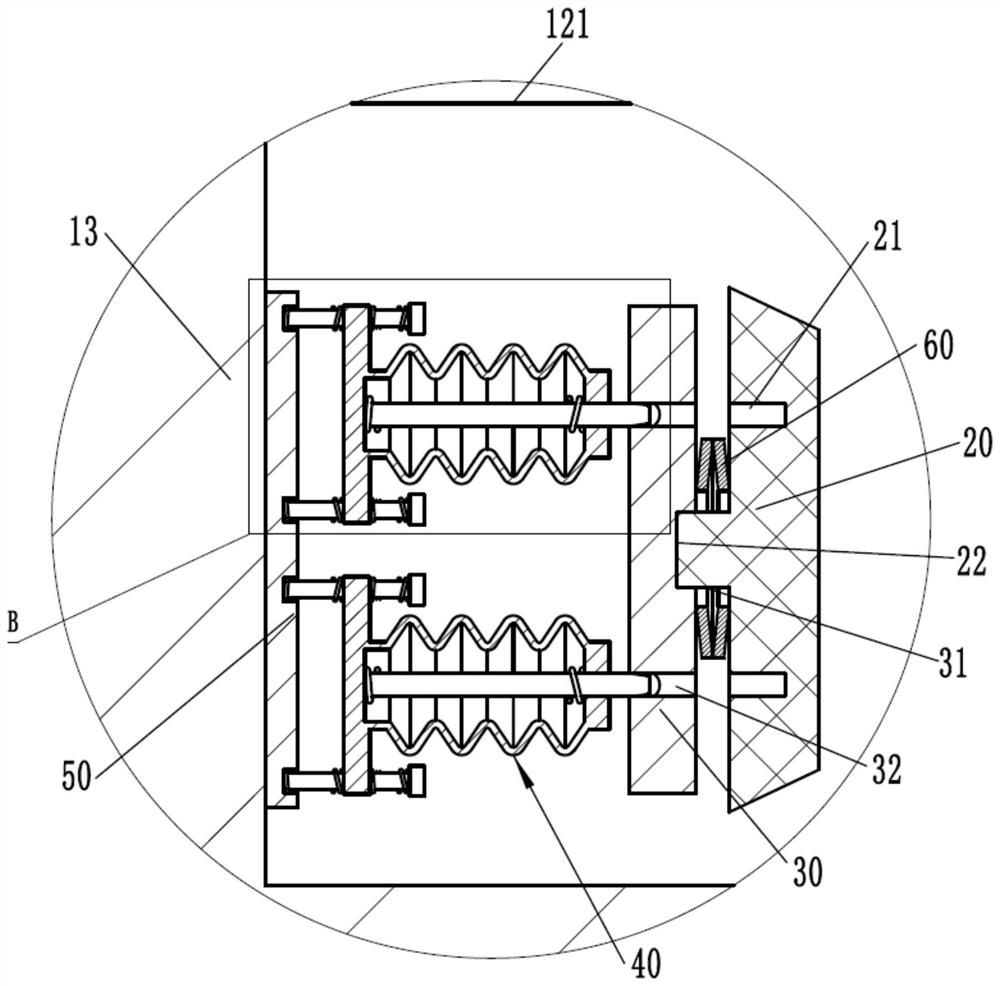
[0032] refer to Figure 1 to Figure 4 ,Such as figure 1 with figure 2 The shown a high-speed braiding machine spindle installation track structure includes a turntable 10 and a pair of buffer assemblies. The outer ring of the turntable 10 is equidistantly fixed with several elongated mounting seats 13, and inside the mounting seats 13 A slide block 11 is slid through the screw mandrel 12, the spindle is installed on the slide block 11, and a pair of buffer ...


PUM


Abstract

The invention discloses a high-speed braiding machine spindle installation track structure, which includes a turntable and a pair of buffer assemblies. The outer ring of the turntable is fixed with several elongated mounting seats at equal intervals, and a pair of buffer assemblies are respectively installed on the On the two side walls of the mounting seat, the buffer assembly includes a bottom plate, a pair of buffer bodies, a top plate and a striking plate, the bottom plate is fixed on the side wall of the mounting seat, and a pair of buffer bodies are slidably arranged on the The front end of the bottom plate, the top plate is slidingly arranged at the front end of a pair of buffer bodies, and the strike plate is connected to the front end of the top plate. Due to the reasonable structure of the present invention, the impact force of the slider can be effectively reduced, making the present invention stable It is better, safer to use, and has a longer service life.

Description

technical field [0001] The invention relates to the technical field of a spindle installation track structure, in particular to a spindle installation track structure for a high-speed knitting machine. Background technique [0002] The spindle is one of the important components of the braiding machine. The quality of the spindle determines the weaving quality of the braiding machine. It not only enables the wire strands to be automatically retracted, but also allows the wire strands to maintain their tension, so that they are firmly attached to the pipe. The current market There are various types of knitting machines on the market, and their structures and functions are quite different. In the prior art, there are knitting machines that can adjust the position of the spindle through the installation track. Drive the screw to rotate, and the screw rotates to drive the sliding seat that matches the screw to move. The spindle is installed on the sliding seat to achieve the purp...

Claims


Application Information

Patent Timeline
Patent Type & Authority Patents(China)
IPC IPC(8): D04C3/00
CPCD04C3/00
Inventor 罗晓晔
Owner HANGZHOU POLYTECHNIC
Why Eureka
Try Eureka