
Three-plate mold

A technology of three-plate mold and backing plate is applied in the field of three-plate mold for injection parts of micro centrifugal pump turbine blades, which can solve the problems of difficult demoulding and incomplete molding of injection parts, and achieve the effect of increasing practicability.

Inactive Publication Date: 2020-06-05
HANGZHOU VOCATIONAL & TECHN COLLEGE
View PDF2 Cites 3 Cited by
  • Summary
  • Abstract
  • Description
  • Claims
  • Application Information

AI Technical Summary

Problems solved by technology

[0003] The purpose of the present invention is to provide a three-plate mold, which can effectively solve the problem of incomplete molding of injection molded parts due to difficulty in demoulding during injection molding of turbine pump blades of micro centrifugal pumps by performing core pulling twice through the core pulling slider assembly

Method used


Image

  • Three-plate mold
  • Three-plate mold
  • Three-plate mold

Examples


Embodiment Construction

[0030] Embodiments of the invention are described in detail below, examples of which are illustrated in the accompanying drawings. The embodiments described below by referring to the figures are exemplary and are intended to explain the present invention and should not be construed as limiting the present invention.

[0031] In describing the present invention, it should be understood that the terms "center", "longitudinal", "transverse", "length", "width", "thickness", "upper", "lower", "front", " The orientation or positional relationship indicated by "rear", "left", "right", "vertical", "horizontal", "top", "bottom", "inner" and "outer" are based on the orientation or position shown in the drawings The positional relationship is only for the convenience of describing the present invention and simplifying the description, but does not indicate or imply that the referred device or element must have a specific orientation, be constructed and operated in a specific orientation,...


PUM


Abstract

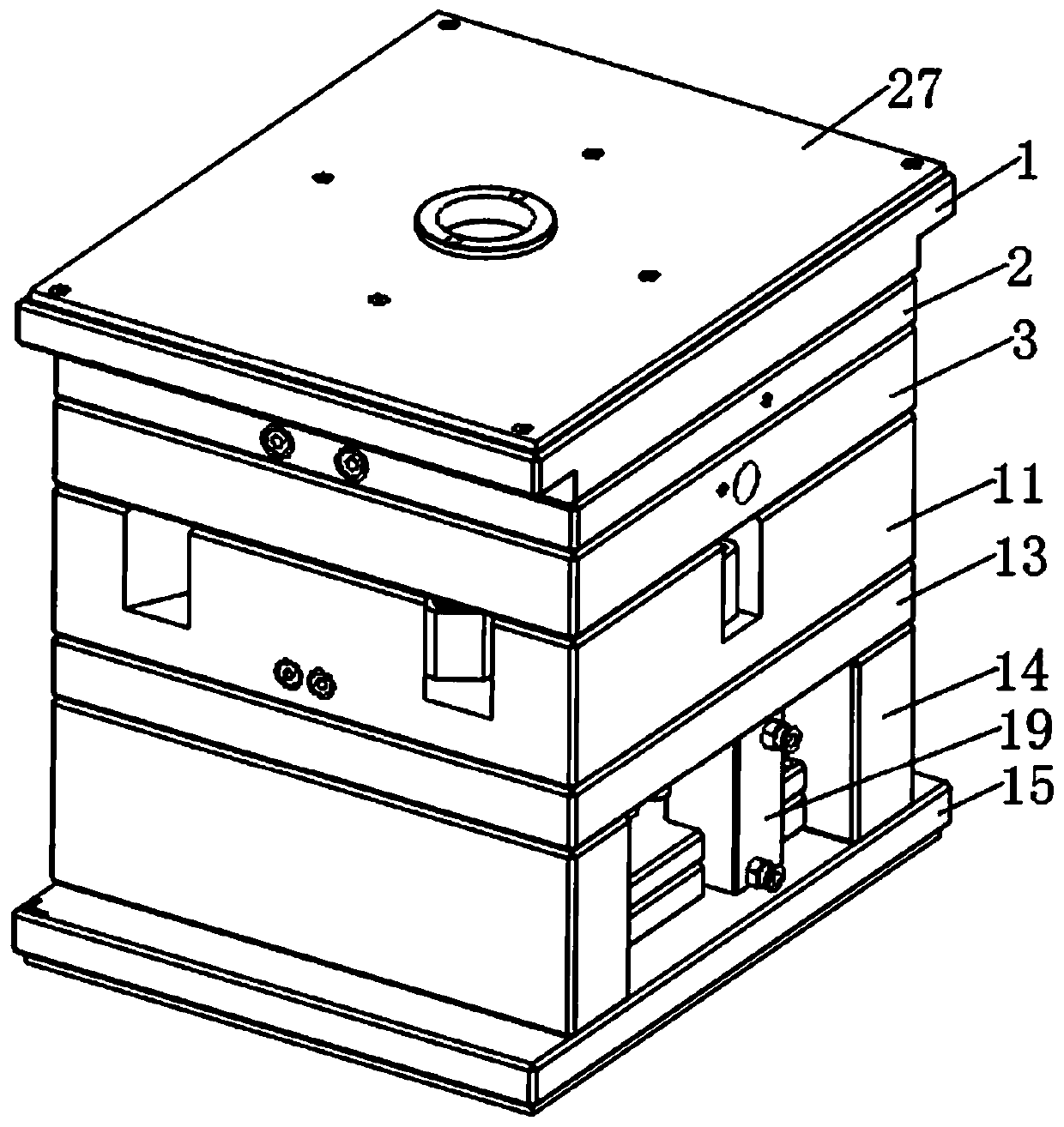
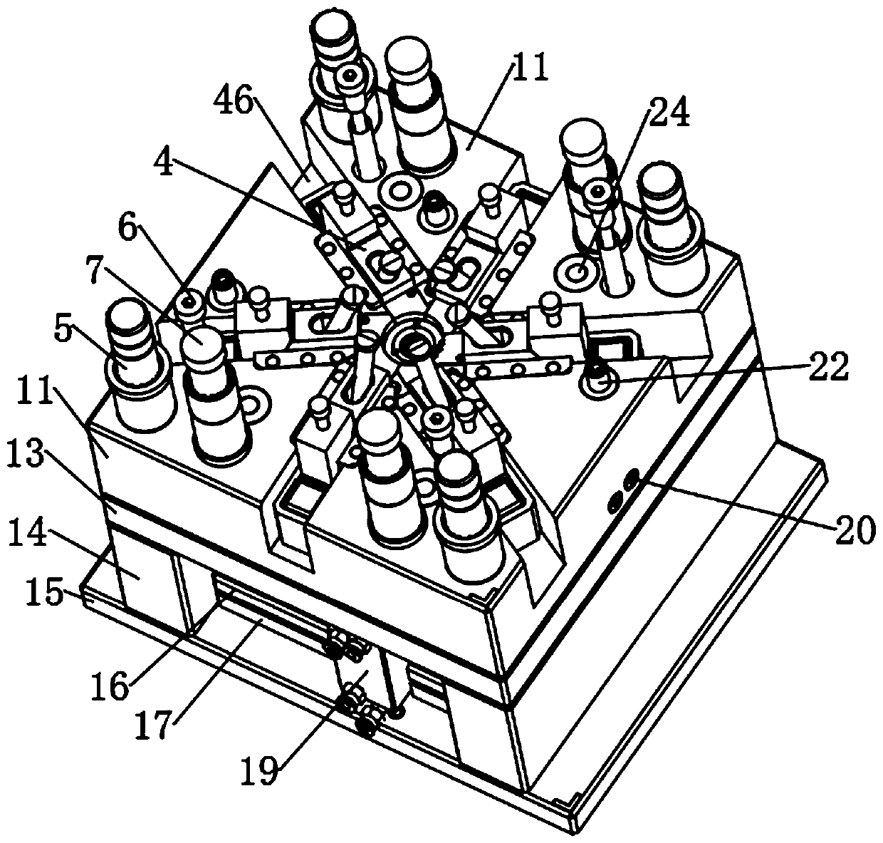
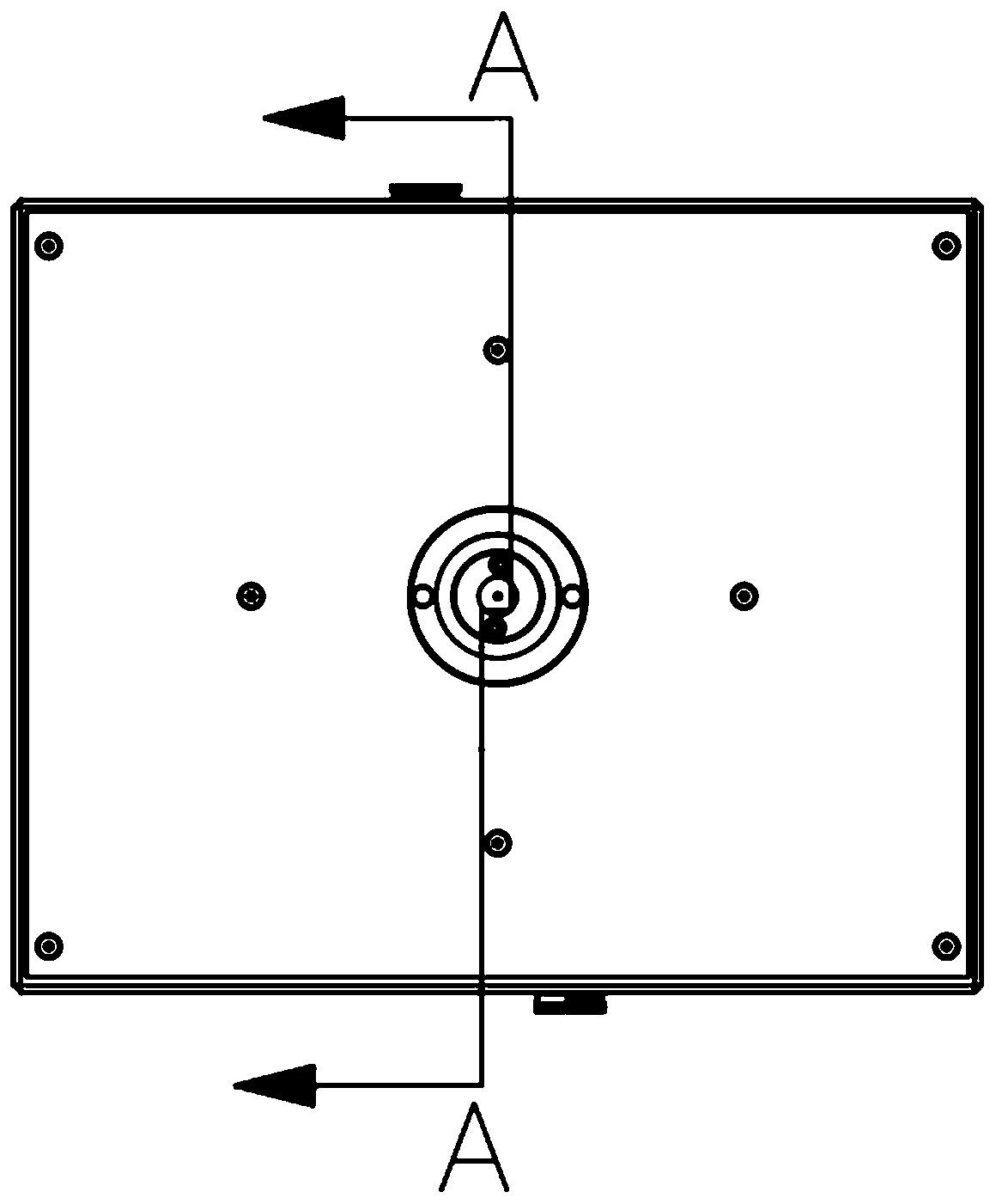
The invention discloses a three-plate mold. The mold sequentially comprises a panel, a stripping plate, a fixed mold plate, a movable mold plate and a movable mold seat plate, six core pulling slidingblock assemblies are mounted in the movable mold plate and are circumferentially surrounded around outside a mold cavity insert and a mold core insert in a manner of being spaced by 60 degrees, eachcore pulling sliding block assembly comprises a first sliding block and a second sliding block in sliding connection with the top of the first sliding block, heads of the first sliding blocks and thesecond sliding blocks extend to the position between the mold cavity insert and the mold core insert, the tops of the second sliding blocks are in sliding connection with third sliding blocks, inclined guide columns used for driving the mold to achieve parting are slidingly mounted in the first sliding blocks, the second sliding blocks, the third sliding blocks and the movable mold plate through guide grooves, and bending pins are fixedly mounted on a movable mold cushion plate. The three-plate mold has the advantages that the movable mold cushion plate is added, the core pulling sliding blockassemblies of a turbine forming part are divided into two layers, core pulling is sequentially carried out, the three-plate mold is improved to four-plate four-time mold opening, and the mold stripping process is more reasonable.

Description

technical field [0001] The invention relates to the technical field of three-plate moulds, in particular to a three-plate mold applied to injection molded parts of turbine blades of micro centrifugal pumps. Background technique [0002] The three-plate mold is widely used in the existing injection molded parts. The main structure of the three-plate mold is parting and demoulding. The traditional three-plate mold is generally divided into three parts. When the traditional mold is applied to the injection molded part of the micro centrifugal pump turbine, there will be demoulding. Difficult problem, the main reason is that the turbine structure of the micro centrifugal pump is relatively complex, and the core-pulling parts of the traditional mold are not easy to pull the core from the vane groove between the vanes. The Chinese utility model whose publication number is CN209320223U discloses a mold opening device for a three-plate mold, including a fixed template, a movable tem...

Claims


Application Information

Patent Timeline
Patent Type & Authority Applications(China)
IPC IPC(8): B29C45/33
CPCB29C45/33B29C45/332
Inventor 杨安
Owner HANGZHOU VOCATIONAL & TECHN COLLEGE
Learn More