Clamping jaw mechanism

A technology of grippers and electro-permanent magnetic chucks, which is applied in the field of automation, can solve the problems of low compatibility of gripper mechanisms, production line downtime, and pipeline air leakage, and achieve the goals of not easy production line downtime, lower failure rates, and saving maintenance costs Effect

Inactive Publication Date: 2020-06-05
SHANGHAI SINYLON AUTO EQUIPMENT MANUFACTURE CO LTD
View PDF6 Cites 3 Cited by
  • Summary
  • Abstract
  • Description
  • Claims
  • Application Information

AI Technical Summary

Problems solved by technology

[0003] The present invention aims at the technical problems that the jaw mechanism in the prior art often causes the production line to stop due to air leakage and insufficient air pressure due to the pneumatic structure, and the gripper mechanism has low compatibility with material differences and high energy consumption. A new jaw mechanism and mechanical gripper

Method used


Image

  • Clamping jaw mechanism
  • Clamping jaw mechanism
  • Clamping jaw mechanism

Examples


Embodiment Construction

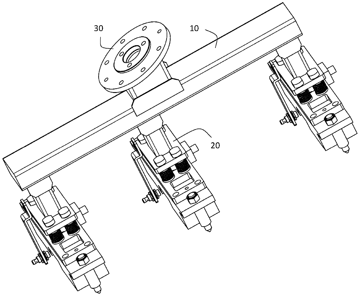
[0031] Such as figure 1 As shown, it is the mechanical gripper of the present invention, including the main beam 10; the flange 30 is fixed in the middle of one side of the main beam 10, and the flange 30 can be fixedly connected with the robot in six axes; several jaw mechanisms 20 are fixedly arranged at an average interval On the other side of the main beam 10.

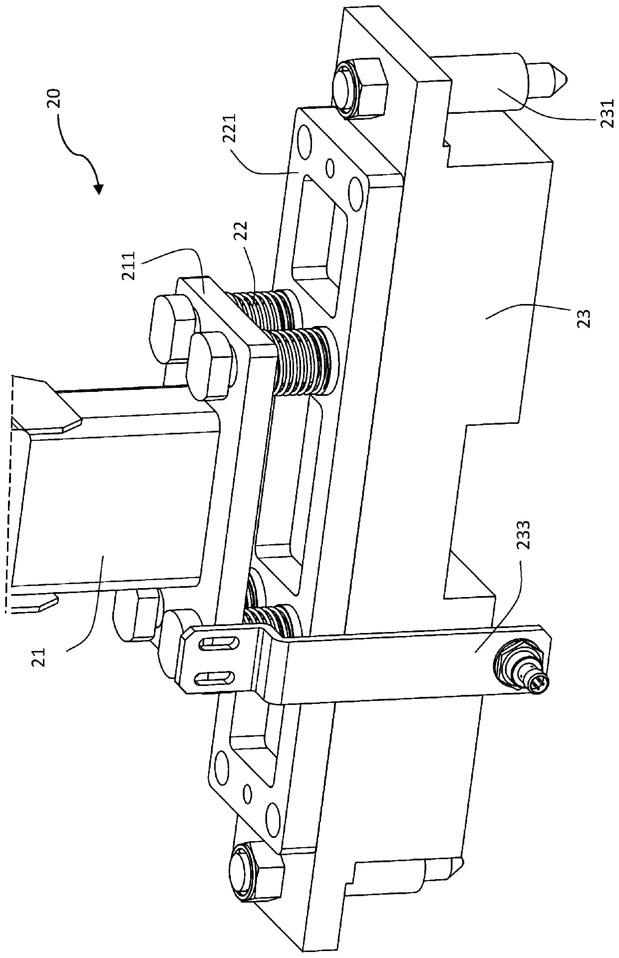
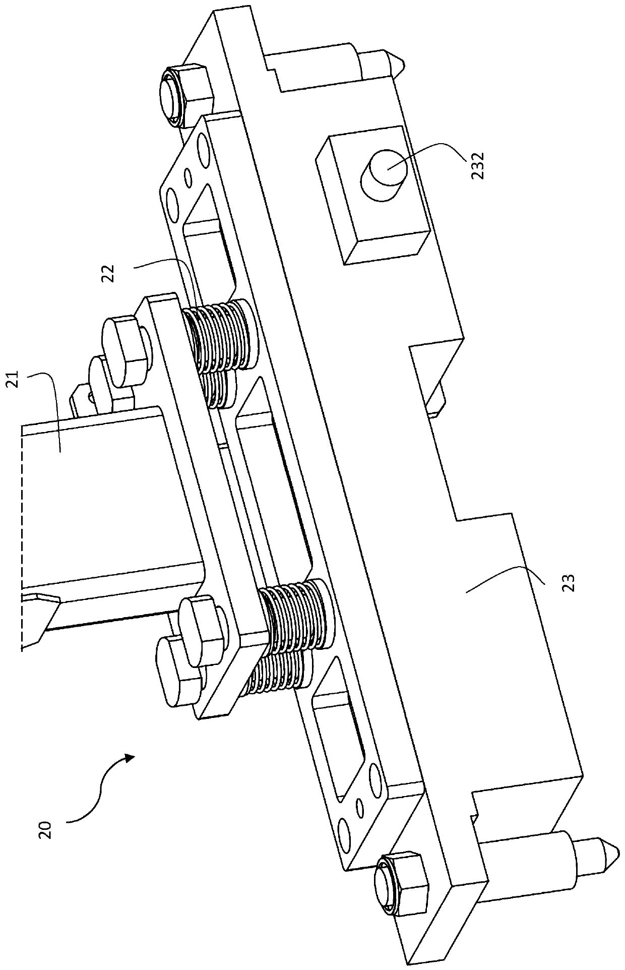
[0032] Such as Figure 2-5 As shown, the jaw mechanism 20 includes a fixed frame 21 , one end wall of the fixed frame 21 is fixed on the other side of the main beam 10 , and the other end wall of the fixed frame 21 is a flat plate 211 . The jaw mechanism 20 includes a float adjustment assembly 22 . One end of the floating adjustment assembly 22 is flexibly connected with the other end wall of the fixing frame 21 in a telescopic manner. The float adjustment assembly 22 has a connecting plate 221 and several guide shafts 222 , and the guide shafts 222 of the float adjustment assembly 22 penetrate and connect to th...


PUM


Abstract

The invention discloses a clamping jaw mechanism. The clamping jaw mechanism comprises a fixing frame, a floating adjusting assembly and an electric permanent magnetic chuck, wherein one end of the floating adjusting assembly is movably connected with the other end wall of the fixing frame in a telescopic mode; and one outer wall of the electric permanent magnetic chuck is fixedly connected with the other end of the floating adjusting assembly, and the other side wall of the electric permanent magnetic chuck can magnetically attract to-be-grabbed materials. According to the clamping jaw mechanism, the production energy consumption can be lower; and compared with a gripper structure adopting an air cylinder or a vacuum chuck, the clamping jaw mechanism of the electric permanent magnetic chuck is simpler, the failure rate is reduced, halt of a production line is not prone to occurring, and therefore the maintenance cost is greatly saved.

Description

technical field [0001] The invention belongs to the technical field of automation, and in particular relates to a claw mechanism with an electric permanent magnetic sucker. Background technique [0002] With the popularization of the automation industry, most of the automobile welding production lines use robots to drive the grippers to replace the traditional manual handling of materials, which greatly saves costs and time and improves production efficiency. The simplification and practicality of the gripper structure greatly reduces the maintenance cost in the production process and reduces the shutdown rate of the production line. The grippers used in the current welding production line generally use multiple cylinders to drive the jaws to carry materials, or use vacuum suction cups to clamp materials. This kind of structure is relatively complicated, requiring compressed air as power, and using directional control valves, throttle valves, etc. for auxiliary control. In...

Claims


Application Information

Patent Timeline
Patent Type & Authority Applications(China)
IPC IPC(8): B25J15/06
CPCB25J15/06B25J15/0608
Inventor 郑永佳谭秀阳韩帆
Owner SHANGHAI SINYLON AUTO EQUIPMENT MANUFACTURE CO LTD
Why Eureka
Try Eureka