Robotic Arms and Medical Robots
A robotic arm and medical device technology, applied in the field of medical devices, can solve the problems of large size, unsatisfactory obstacle avoidance ability, heavy weight, etc., and achieve the effect of small overall size, light weight, and easy installation and use
- Summary
- Abstract
- Description
- Claims
- Application Information
AI Technical Summary
Problems solved by technology
Method used
Image

Examples
Embodiment 1
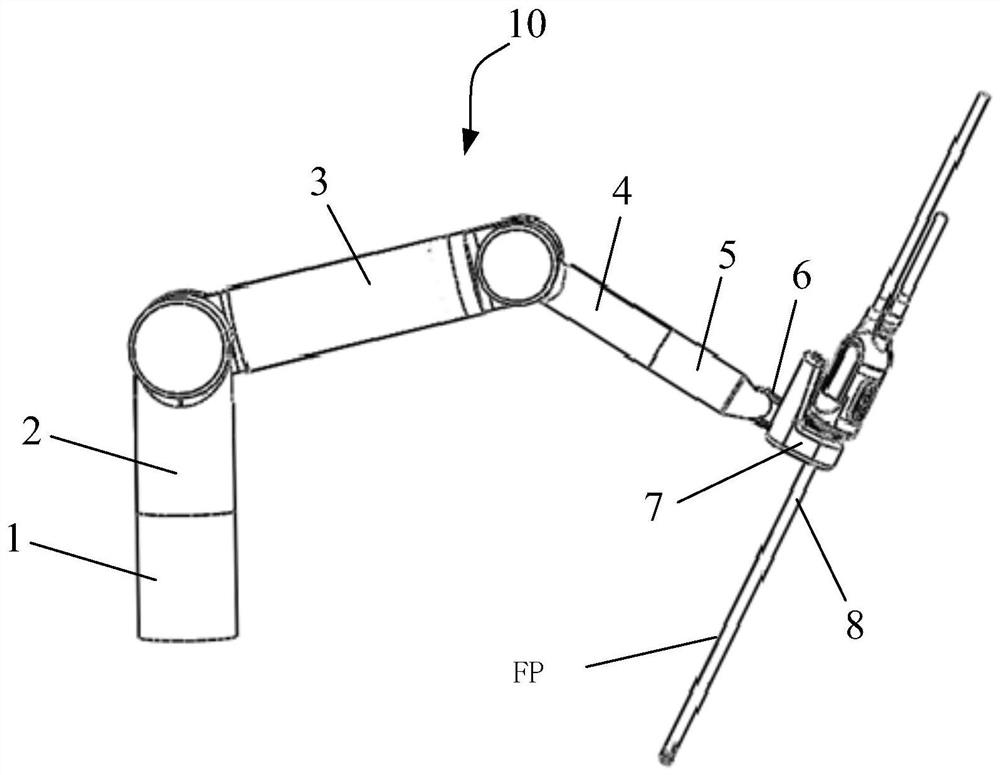
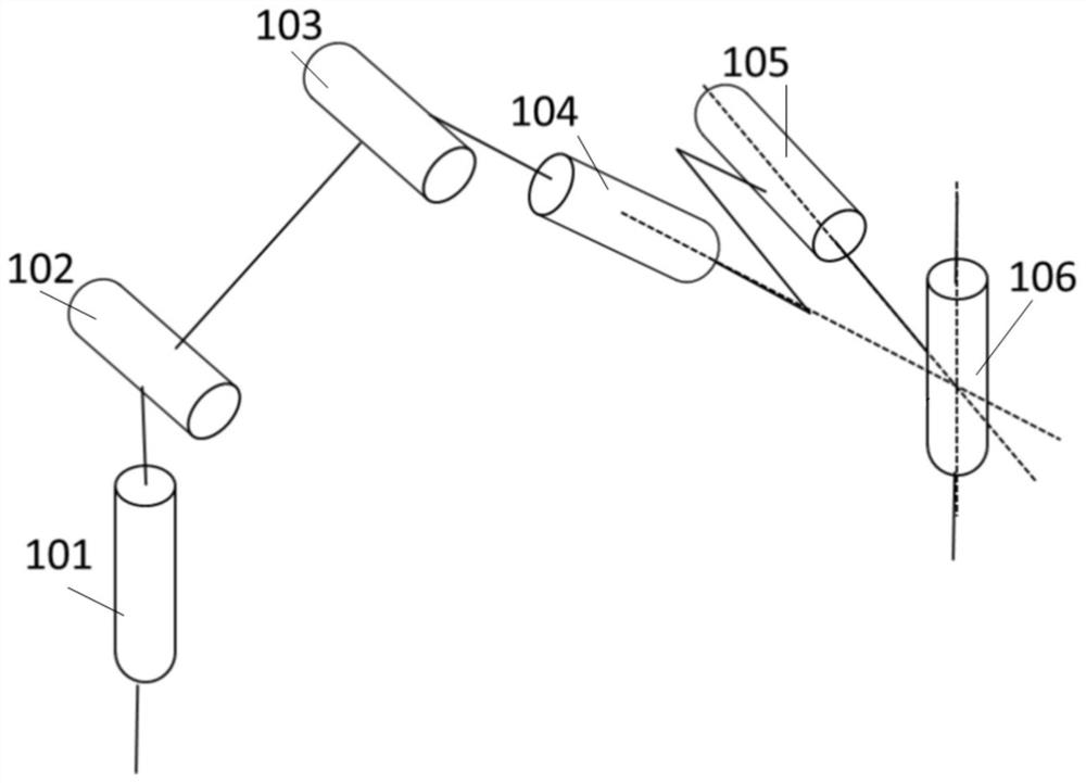
[0075] like figure 1 and figure 2 As shown, in the first embodiment of the present invention, a medical robot 10 is provided, which includes a mechanical arm and a medical device detachably connected to the end of the mechanical arm. In this embodiment, the medical device is a laparoscope 8, so The robotic arm is used to drive the laparoscope 8 to move around a fixed point. From the proximal end to the distal end, the robotic arm sequentially includes a first rotating joint 101 , a first swinging joint 102 , a second swinging joint 103 , a second rotating joint 104 , and a third swinging joint 105 . The autorotation joint 106 that rotates.
[0076] The rotation axis of the first pivot joint 101 is perpendicular to and intersects with the rotation axis of the first pivot joint 102; the rotation axis of the first pivot joint 102 is parallel to the rotation axis of the second pivot joint 103; the second pivot joint 103 The rotational axis of the second rotational joint 104 is...
Embodiment 2
[0087] The robotic arm of the embodiment of the present invention is basically the same as that of the first embodiment, and the following mainly focuses on the differences.
[0088] like Figure 3a and Figure 3b As shown, in the second embodiment of the present invention, some of the links in the robotic arm are offset connections. Specifically, in Figure 3b In the top view angle shown, the middle arm 3 is located on the right side of the big arm 2, and the forearm 4 is located on the left side of the middle arm 3, that is, the axis of the middle arm 3 and the axis of the big arm 2 do not intersect, that is, the different The axis of the forearm 4 does not intersect with the axis of the middle arm 3, that is, different planes or parallel. Preferably, the axis of the large arm 2 and the axis of the forearm 4 are located on the same side of the axis of the middle arm 3 . For example, the large arm 2 and the forearm 4 are both located on the left side of the middle arm 3 (...
Embodiment 3
[0090] The robotic arm of the embodiment of the present invention is basically the same as that of the first embodiment, and the following mainly focuses on the differences.
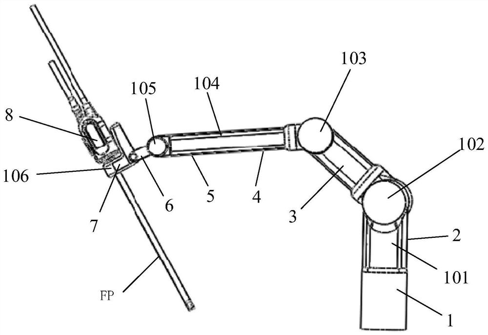
[0091] like Figure 4 As shown, in the third embodiment of the present invention, the rotation axis of the second rotation joint 104, the rotation axis of the third swing joint 105 and the rotation axis of the autorotation joint 106 do not intersect at one point, specifically the second rotation joint The rotation axis of 104 is perpendicular to and intersects with the rotation axis of the third swing joint 105 , the rotation axis of the third swing joint 105 and the rotation axis of the autorotation joint 106 are only perpendicular but not intersecting, and the rotation axis of the second rotation joint 104 Only the axis of rotation of the autorotation joint 106 is intersected.
[0092] At this time, the mirror base connector 6 is an optional solution, that is, the forearm 5 can be directly connected t...
PUM
 Abstract
Description
Claims
Application Information
 - R&D
- Intellectual Property
- Life Sciences
- Materials
- Tech Scout
- Unparalleled Data Quality
- Higher Quality Content
- 60% Fewer Hallucinations
Browse by: Latest US Patents, China's latest patents, Technical Efficacy Thesaurus, Application Domain, Technology Topic, Popular Technical Reports.
© 2025 PatSnap. All rights reserved.Legal|Privacy policy|Modern Slavery Act Transparency Statement|Sitemap|About US| Contact US: help@patsnap.com