
Height milling device

A technology of milling height and milling cutter, applied in milling machine equipment, details of milling machine equipment, metal processing equipment, etc., can solve problems such as low production efficiency, worker safety concerns, and the inability of raised floors to fit closely.

Pending Publication Date: 2020-06-02
ベロテクノロジーズドンタイカンパニーリミテッド
View PDF0 Cites 3 Cited by
  • Summary
  • Abstract
  • Description
  • Claims
  • Application Information

AI Technical Summary

Problems solved by technology

During the molding process, there will be many burrs on the surface and bottom of the raised floor. During the installation process, these blemishes and burrs will prevent the raised floor from being tightly fitted or the platform frame. On the one hand, it is not conducive to workers' installation, and there will be certain safety concerns for workers
[0003]However, in the existing method, it is necessary to manually remove the burrs from the four feet of the formed raised floor, which not only has low production efficiency, but also It takes a lot of manpower and time-consuming

Method used

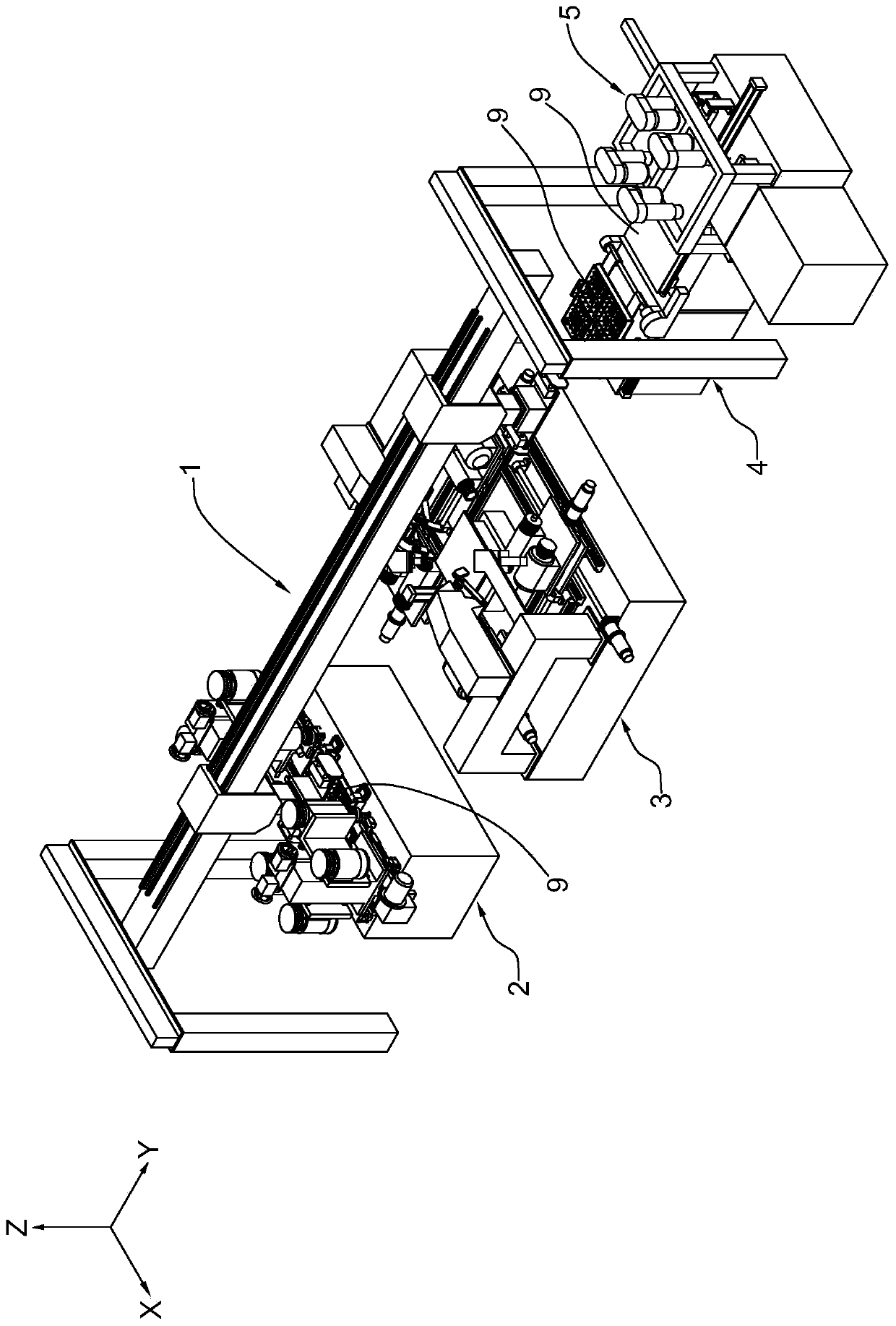
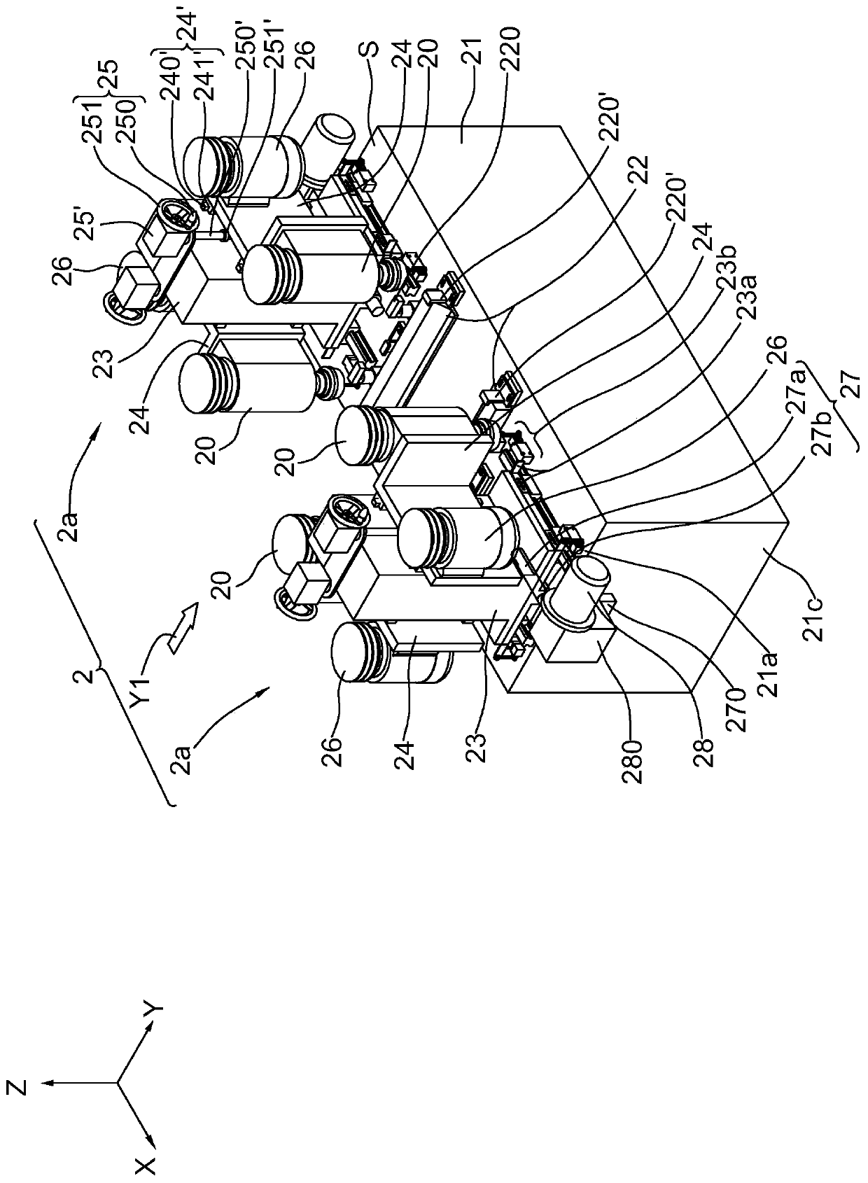
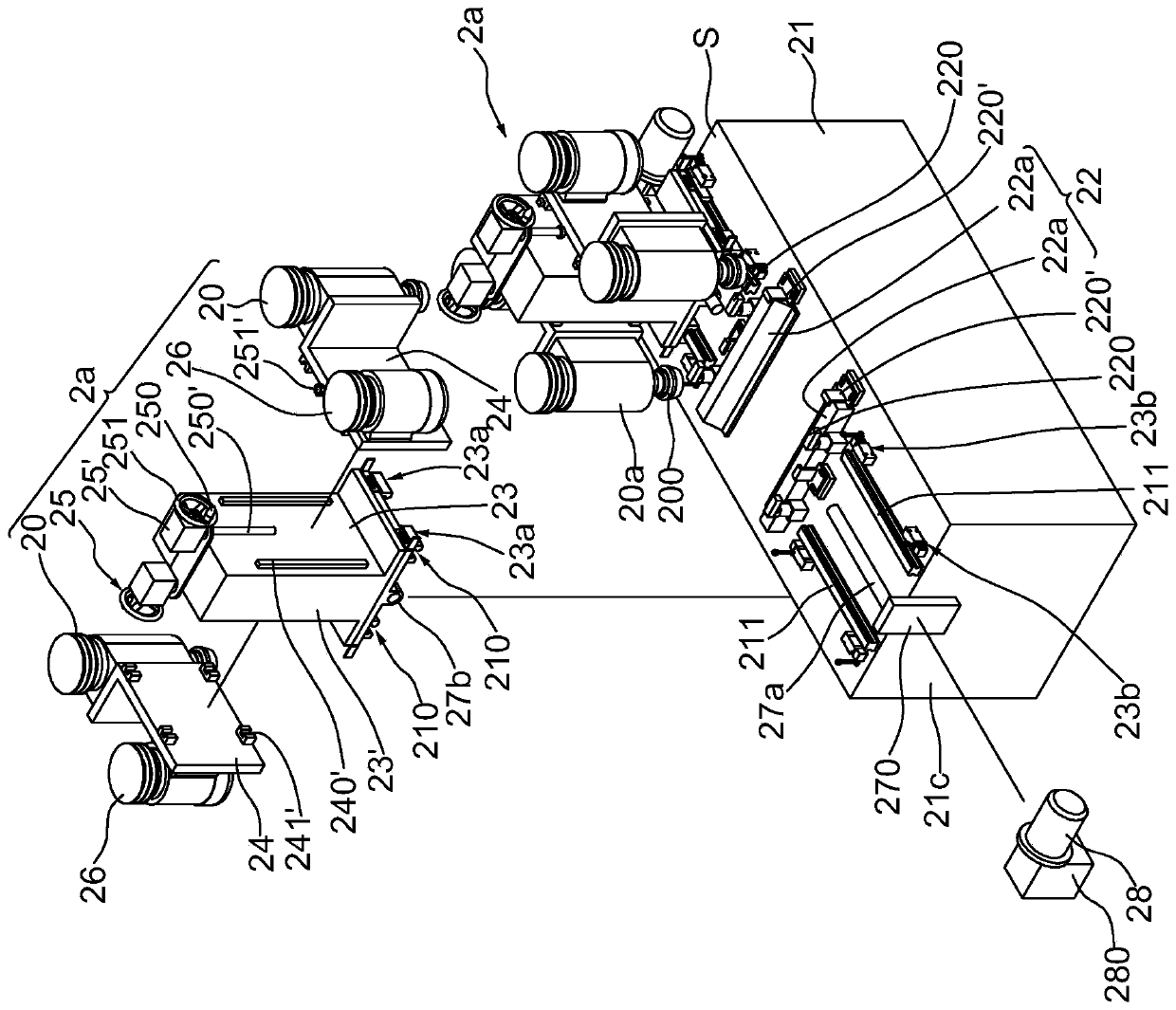

Image

  • Height milling device
  • Height milling device
  • Height milling device

Examples


Embodiment Construction

[0032] The implementation of the present invention is described below through specific specific examples, and those skilled in the art can easily understand other advantages and effects of the present invention from the content disclosed in this specification.

[0033] It should be noted that the structures, proportions, sizes, etc. shown in the drawings attached to this specification are only used to match the content disclosed in the specification, for the understanding and reading of those familiar with this technology, and are not used to limit the implementation of the present invention Therefore, it has no technical substantive meaning. Any modification of structure, change of proportional relationship or adjustment of size shall still fall within the scope of this invention without affecting the effect and purpose of the present invention. The technical content disclosed by the invention must be within the scope covered. At the same time, terms such as "upper", "lower",...


PUM


Abstract

The invention discloses a height milling device. The height milling device comprises a base table with a working face and at least one height milling assembly arranged on the working face in a displaceable mode, wherein height machining treatment is carried out on a target object through the height milling assemblies, so that the production time is shortened, the production efficiency is improved,and the labor cost is reduced.

Description

technical field [0001] The invention relates to a machine tool for processing burrs, in particular to a height milling device. Background technique [0002] At present, raised floor devices are widely used in anti-static computer rooms or clean rooms. Among them, the existing aluminum alloy die-cast raised floor needs to go through five main processes such as mold opening, aluminum melting, die-casting, molding, and trimming. . During the forming process, there will be many burrs on the surface and bottom of the raised floor. During the installation process, these blemishes and burrs will prevent the raised floor from being tightly fitted or the platform frame. On the one hand, it is not conducive to workers' installation, and there will be certain safety concerns for workers. [0003] However, in the existing method, it is necessary to manually remove the burrs of the four feet of the formed elevated floor, which not only has low production efficiency, but also wastes a l...

Claims


Application Information

Patent Timeline
Patent Type & Authority Applications(China)
IPC IPC(8): B23C3/12B23C3/00
CPCB23C3/00B23C3/12
Inventor 黄建德
Owner ベロテクノロジーズドンタイカンパニーリミテッド
Learn More