
Iron removal device and iron removal equipment with the same

A technology of equipment and cleaning devices, which is applied in the field of separation and can solve problems such as difficult cleaning of iron removers

Pending Publication Date: 2020-05-29
浙江软控智能科技有限公司
View PDF0 Cites 0 Cited by
  • Summary
  • Abstract
  • Description
  • Claims
  • Application Information

AI Technical Summary

Problems solved by technology

[0005] The main purpose of the present invention is to provide an iron removal device and its iron removal equipment to solve the problem that the iron remover in the prior art is difficult to clean

Method used


Image

  • Iron removal device and iron removal equipment with the same
  • Iron removal device and iron removal equipment with the same

Examples


Embodiment Construction

[0023] It should be noted that, in the case of no conflict, the embodiments in the present application and the features in the embodiments can be combined with each other. The present invention will be described in detail below with reference to the accompanying drawings and examples.

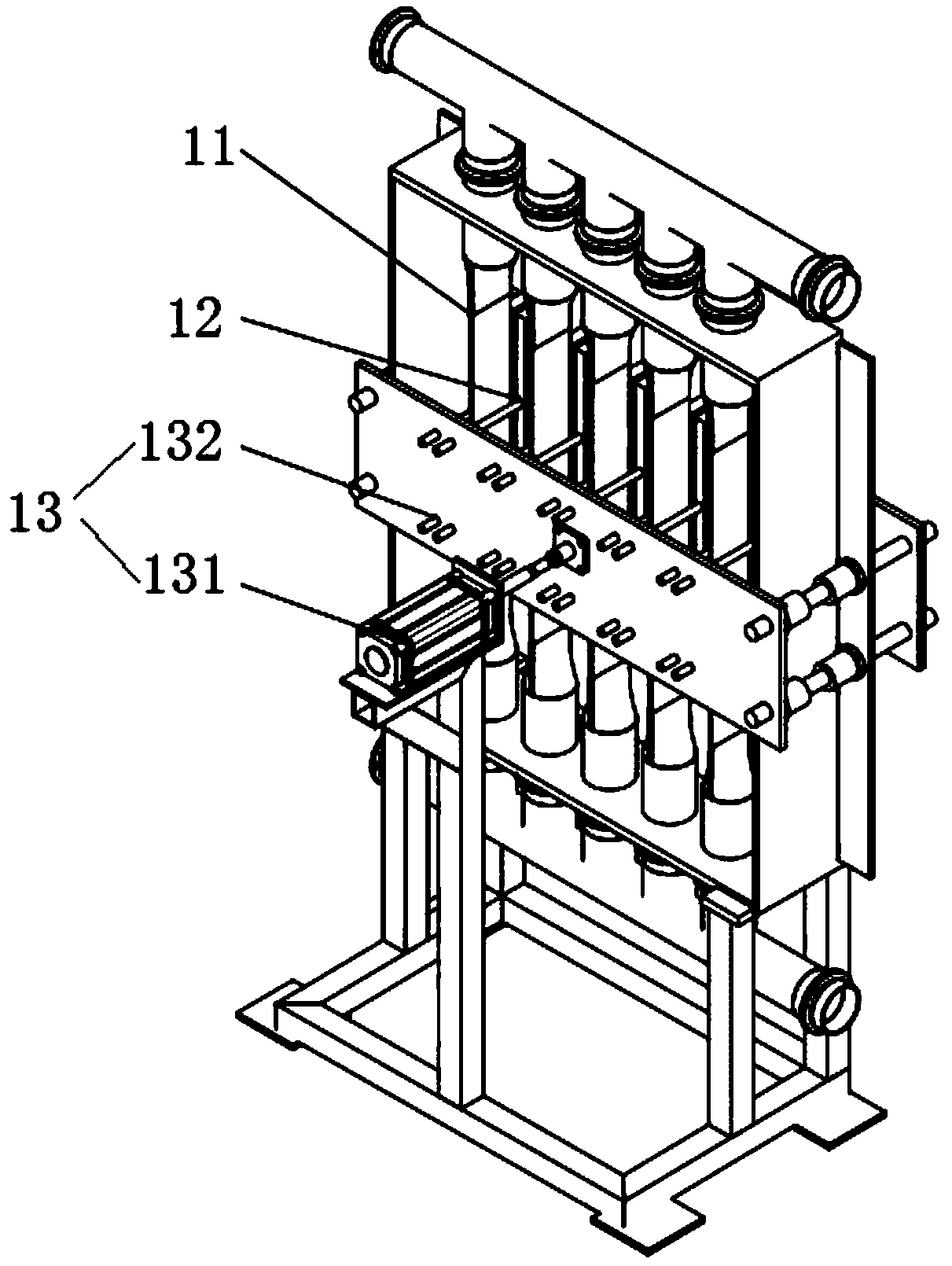
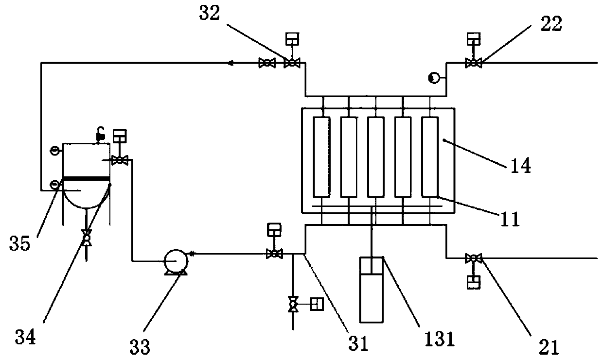
[0024] The invention provides a device for removing iron, which is used to take out the iron material in the material, please refer to figure 1 with figure 2 , the iron removal device includes: a material flow channel 11, the material moves in the material flow channel 11; a magnetic plate assembly 12, the magnetic plate assembly 12 is arranged on the outside of the material flow channel 11, for absorbing the material in the material flow channel 11 On the inner wall of the material flow channel 11.

[0025] The iron removal device of the present invention is mainly used to remove iron impurities in materials containing iron impurities. The iron removal device includes a material flow channe...


PUM


Abstract

The invention provides an iron removal device and iron removal equipment with the same. The iron removal device is used for taking out iron materials in materials. The iron removal device comprises amaterial flow channel and a magnetic plate assembly, wherein the materials move in the material flow channel; and the magnetic plate assembly is arranged on an outer side of the material flow channeland used for adsorbing the materials in the material flow channel to an inner wall of the material flow channel. The iron removal device solves a problem that an iron remover in the prior art is difficult to clean.

Description

technical field [0001] The invention relates to the technical field of separation, in particular, to an iron removal device and iron removal equipment equipped with the iron removal device. Background technique [0002] The iron remover is a device that can generate a strong magnetic field attraction. It can remove ferromagnetic impurities mixed in the material. The ferromagnetic impurities are adsorbed to the magnet to avoid entering the downstream link. It can be used in lithium batteries, food, and medicine. and other industries. [0003] The iron remover in the prior art has a pressure-resistant cavity, and the magnetic rod is fixed in the cavity, and the material medium to be removed flows between the positions where the magnetic rod is fixed in the iron remover cavity, and through the contact between the medium and the magnet Adsorb iron impurities. After the equipment is out of use, manually disassemble the magnetic rod, remove the impurities on the magnetic rod, an...

Claims


Application Information

Patent Timeline
IPC IPC(8): B03C1/26
CPCB03C1/26
Inventor 李学奎杨敏周军
Owner 浙江软控智能科技有限公司
Learn More