
High-temperature-resistant spark plug for lean gas

A technology for spark plugs and high temperature resistance, which is applied in the direction of spark plugs, electrical components, circuits, etc. It can solve the problems of increased damage rate, inability to effectively help exhaust gas discharge, spark plugs cannot be stably ignited, etc., and achieve the effect of preventing accumulation

Active Publication Date: 2020-05-26
MXTL CO LTD
View PDF4 Cites 0 Cited by
  • Summary
  • Abstract
  • Description
  • Claims
  • Application Information

AI Technical Summary

Problems solved by technology

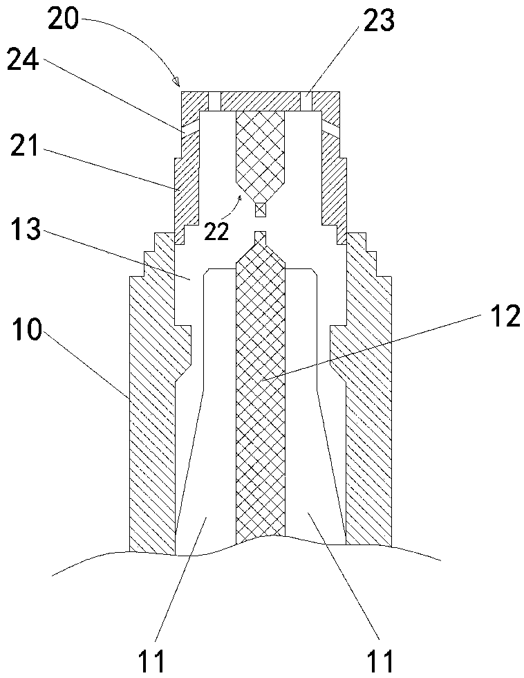
However, after the hollow cavity 13 is ignited, the center of the top of the negative ignition unit is the area where the heat is most concentrated. After multiple ignitions, the electrodes of the negative ignition unit are always in a high-temperature environment, resulting in a greatly increased damage rate.
[0005] 2) The housing side wall of the above-mentioned spark plug is provided with a plurality of exhaust gas outlets 24, but the accumulation of exhaust gas is mainly at the bottom of the hollow cavity 13. After fresh air enters from the top of the housing of the negative ignition unit 20 and ignites, The exhaust gas outlet 24 provided on the upper part of the side wall of the housing cannot effectively help the discharge of exhaust gas; resulting in the accumulation of exhaust gas at the bottom of the hollow cavity 13, which hinders the effective ignition of the spark plug
[0006] 3) When the gas in the cylinder is a rare gas, the existing spark plug cannot be ignited stably

Method used


Image

  • High-temperature-resistant spark plug for lean gas
  • High-temperature-resistant spark plug for lean gas
  • High-temperature-resistant spark plug for lean gas

Examples


Embodiment 1

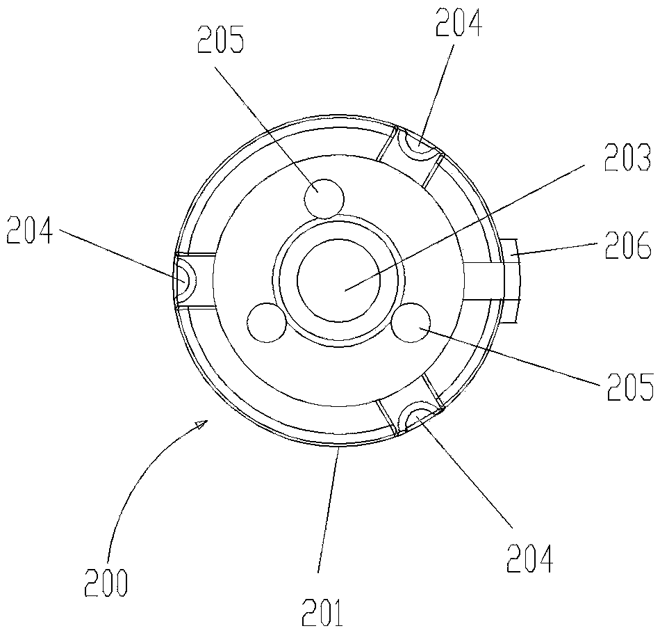
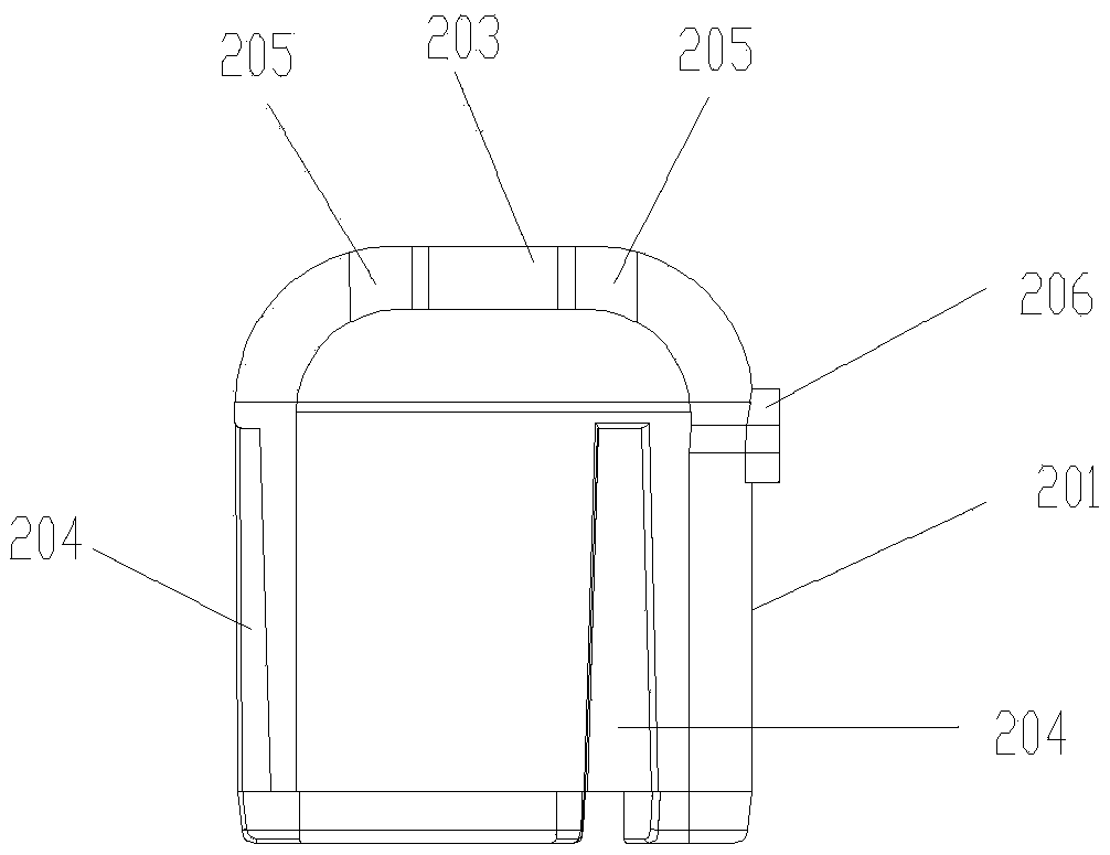
[0026] see figure 2 As shown, a high-temperature resistant spark plug 100 for rare gas includes a spark plug shell 101, an insulator 102 and a central electrode 103; , the central electrode 103 is covered in the insulator 102, the top of the central electrode 103 extends through the insulator 102 and is exposed in the hollow cavity 104 of the spark plug shell 101; a negative ignition unit 200 is arranged above the central electrode 103, The negative ignition unit 200 includes a housing 201 and a negative electrode 202; the lower end of the housing 201 is embedded into the spark plug housing 101 and fixed, and the cavity in the housing 201 and the hollow cavity 104 in the spark plug housing form an expansion chamber; A central air vent 203 is provided at the center of the bottom surface of the housing 201 of the negative ignition unit 200, and a longitudinal arc-shaped groove 204 is provided on the outer wall of the housing 201, and the arc-shaped groove 204 extends from the h...


PUM


Abstract

The invention discloses a high-temperature-resistant spark plug for lean gas. The high-temperature-resistant spark plug comprises a spark plug shell, an insulator and a central electrode, wherein a negative electrode ignition unit is arranged above the central electrode and comprises a shell and a negative electrode; the lower end of the shell is embedded into the spark plug shell to be fixed, anda cavity in the shell and a hollow cavity in the spark plug shell form an expansion cavity; a central exhaust hole is formed in the center of the bottom surface of a shell of the negative electrode ignition unit, a longitudinal arc-shaped groove is formed in the outer side wall of the shell, and the arc-shaped groove extends from the lower end of the shell to the upper end, which is not wrapped by the spark plug shell, of the shell; a horizontally-arranged negative electrode is arranged on the shell, and an ignition distance is reserved between the end of the negative electrode and the top end of the central electrode. According to the high-temperature-resistant spark plug, the heat accumulation phenomenon does not occur at the top end of the negative electrode ignition unit any more, itis guaranteed that the negative electrode is not damaged due to overheating, and waste gas is effectively prevented from accumulating in the hollow cavity; and the thin gas in the cylinder can be stably ignited.

Description

technical field [0001] The invention relates to the field of spark plugs for automobiles, in particular to a high-temperature-resistant spark plug for rare gas. Background technique [0002] see figure 1 As shown, the Chinese patent No. 201621291326.5 "a kind of spark plug" discloses a spark plug, including a spark plug shell 10, an insulator 11 and a central electrode 12; the spark plug shell is provided with a hollow cavity 13, and the insulator 11 is fixed in the hollow cavity 13, the central electrode 12 is covered in the insulator 11, and the top of the central electrode 12 extends through the insulator 11 and is exposed in the hollow cavity 13 of the spark plug shell 10; Unit 20, the negative electrode ignition unit 20 includes a housing 21 and a negative electrode 22; the lower end of the housing 21 is fixedly connected to the upper end of the spark plug housing 10, such as welding, screwing, etc.; the cavity in the housing 21 and The hollow cavity 13 in the spark p...

Claims


Application Information

Patent Timeline
IPC IPC(8): H01T13/06H01T13/32H01T13/02
CPCH01T13/02H01T13/06H01T13/32
Inventor 柳孟柱刘全
Owner MXTL CO LTD
Learn More