
A road curb installation equipment

A technology for curb stones and roads, applied in the field of road curb stone laying equipment, can solve the problems of increasing curb stone laying accuracy and poor curb stone laying effect, and achieves increased laying accuracy, high laying continuity, and increased pushing effect. Effect

Active Publication Date: 2020-10-13
中源宏宇建设集团有限公司
View PDF8 Cites 0 Cited by
  • Summary
  • Abstract
  • Description
  • Claims
  • Application Information

AI Technical Summary

Problems solved by technology

[0008] The middle part of the limit bolt is connected with the middle part of the upper end of the limit adjustment frame by thread fit, and the rear end of the limit bolt is installed on the upper front side of the limit support frame through a bearing. During specific work, the limit mechanism can make The present invention moves along the paved curb stones, thereby increasing the laying accuracy of the curb stones, and the position of the limit adjustment frame can be adjusted by turning the limit bolts, so that the present invention can be laid for curb stones of different widths, and the sliding column It can limit the position of the limit adjustment frame to prevent the angle change when the limit adjustment frame is adjusted, resulting in poor laying effect of curb stones and other problems

Method used


Image

  • A road curb installation equipment
  • A road curb installation equipment
  • A road curb installation equipment

Examples


Embodiment Construction

[0029] In order to make the technical means, creative features, goals and effects achieved by the present invention easy to understand, the present invention will be further described below in conjunction with specific illustrations. It should be noted that, in the case of no conflict, the embodiments in the present application and the features in the embodiments can be combined with each other.

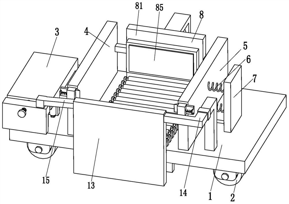
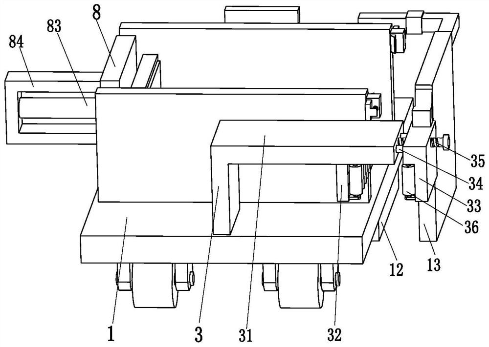
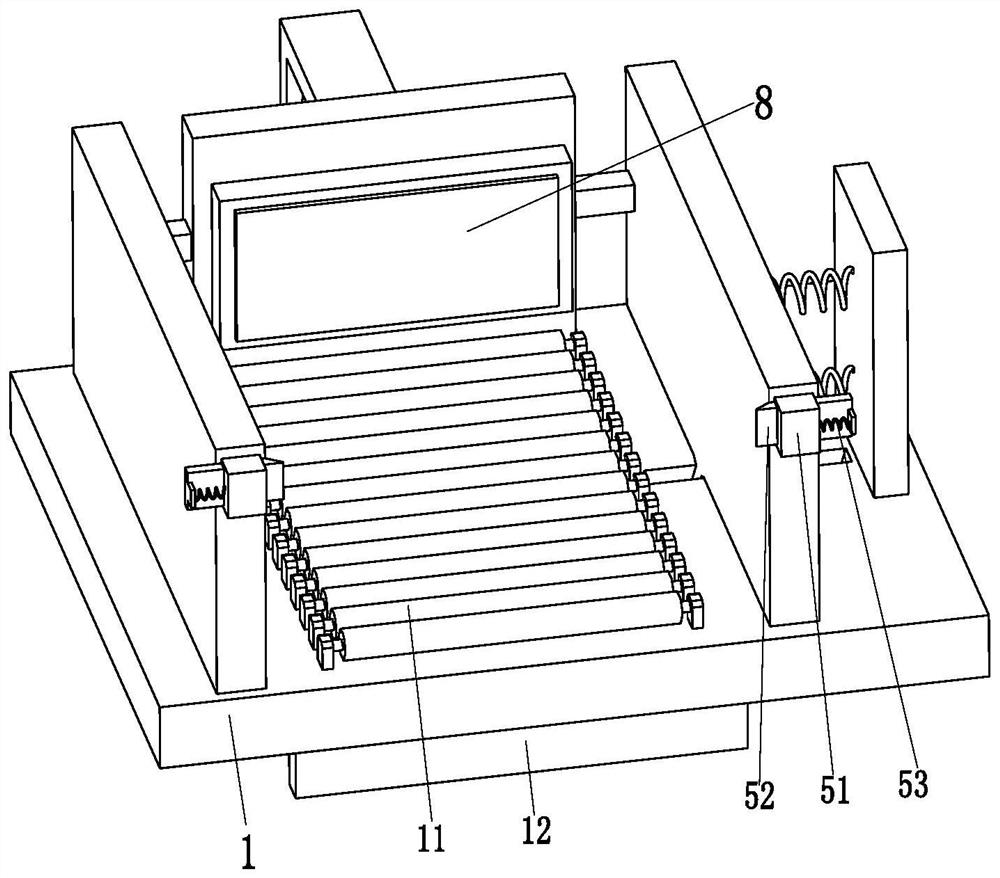
[0030] Such as Figure 1 to Figure 5As shown, a road curb installation equipment includes a walking support plate 1, a traveling wheel 2, a limit mechanism 3, a fixed plate 4, a sliding plate 5, a sliding spring 6, a spring support plate 7 and a pushing mechanism 8, the Walking wheels 2 are installed symmetrically on the bottom of the walking support plate 1, the limit mechanism 3 is installed on the left end top of the walking support plate 1, the fixed plate 4 is located on the right side of the limit mechanism 3, the fixed plate 4 and the walking support plate 1 The top of the wa...


PUM


Abstract

The invention relates to road kerb mounting and building equipment which comprises a walking support plate, walking wheels, a limiting mechanism, a fixed plate, a sliding plate, sliding springs, a spring support plate and a pushing mechanism. The walking wheels are symmetrically mounted at the bottom of the walking support plate. The limiting mechanism is mounted at the top of the left end of thewalking support plate. The fixed plate is connected with the top of the walking support plate. A sliding groove is transversely formed in the top of the right end of the walking supporting plate, andthe sliding groove of the walking supporting plate is connected with the sliding plate in a sliding fit mode. The right side face of the sliding plate is connected with the spring support plate through the sliding springs, and the spring support plate is installed at the top of the right end of the walking support plate. The pushing mechanism is installed at the top of the rear end of the walkingsupport plate. The problems in existing kerb laying can be solved, namely, the kerbs need to be carried and placed manually, the kerb laying continuity is low, the manual workload is large due to manual carrying of the kerbs, and certain potential safety hazards exist.

Description

technical field [0001] The invention relates to the field of municipal construction, in particular to a road curb installation equipment. Background technique [0002] Curb stones are marker stones laid between the road surface and other structures; curb stones are generally required between the separation strip of urban roads and the road surface, and between the sidewalk and the road surface. There are usually two forms of curb stones, one is Ordinary concrete prefabrication, one is stone processing, and they are all impermeable materials. [0003] When laying curb stones, it is necessary to dig a placement groove on the outside of the road. The width of the placement groove is slightly larger than the width of the curb stone. The height of the curb stone is generally higher than the height of the road. The curb stone is generally laid manually. Manually place the curb stones on the road that needs to be paved, then manually lift the curb stones into the placement groove,...

Claims


Application Information

Patent Timeline
Patent Type & Authority Patents(China)
IPC IPC(8): E01C19/52
CPCE01C19/52
Inventor 吴锋华代德伟葛江波
Owner 中源宏宇建设集团有限公司
Learn More