
Concrete mixing device with cleaning function

A mixing device and concrete technology, which is applied in the direction of cement mixing device, clay preparation device, cleaning hollow objects, etc., can solve the problems of insufficient and different batching process research, and achieve the effect of convenient operation, simple structure and labor saving

Active Publication Date: 2020-05-19
景德镇市黑猫资源综合利用有限责任公司
View PDF8 Cites 5 Cited by
  • Summary
  • Abstract
  • Description
  • Claims
  • Application Information

AI Technical Summary

Problems solved by technology

[0002] Concrete mixing is an operation method that mixes cement, lime, water and other materials and mixes them evenly. Concrete mixing is divided into two types: manual mixing and mechanical mixing of water. Concrete mixing stations are widely used in my country's industry, agriculture, transportation, national defense, In water conservancy, municipal and other construction projects, the demand is constantly increasing. Although domestic concrete mixing equipment is constantly innovating and improving on the basis of foreign products, and the technical level is gradually improving, as far as the entire mixing station is concerned, the research on the batching process is still insufficient. Especially for newly-built concrete mixing plants, they often rely on the experience accumulated by supporting manufacturers for many years, and basically meet the quality requirements of national standards for concrete mixing plants. There is no special experimental research on its conveying process and feeding process. Different concrete There are different mixing ratios, and new mixing buckets are required when mixing different ratios of concrete

Method used


Image

  • Concrete mixing device with cleaning function
  • Concrete mixing device with cleaning function
  • Concrete mixing device with cleaning function

Examples


Embodiment Construction

[0016] All features disclosed in this specification, or steps in all methods or processes disclosed, may be combined in any manner, except for mutually exclusive features and / or steps.

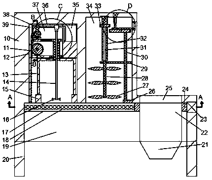
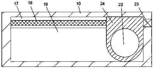
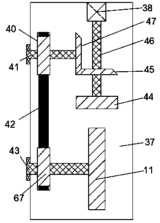
[0017] Combine below Figure 1-5 The present invention is described in detail, and for convenience of description, the orientations mentioned below are now stipulated as follows: figure 1 The up, down, left, right, front and back directions of the projection relationship itself are the same.

[0018] A concrete mixing device with a cleaning function of the device of the present invention includes a main body 10, four brackets 20 are arranged at the lower end of the main body 10, a first sliding cavity 39 is arranged inside the main body 10, and the first sliding cavity 39 A cleaning assembly is provided inside, and a second sliding chamber 34 located on the right side of the first sliding chamber 39 is provided inside the main body 10, and a stirring assembly is arranged inside the second sli...


PUM


Abstract

The invention relates to the field of concrete mixing, in particular to a concrete mixing device with a cleaning function. The concrete mixing device comprises a main body. The lower end of the main body is provided with four supports. The main body is internally provided with a first sliding cavity. A cleaning assembly is arranged in the first sliding cavity. The main body is internally providedwith a second sliding cavity located on the right side of the first sliding cavity. A mixing assembly is arranged in the second sliding cavity. A third sliding cavity of which the upper end communicates with the first sliding cavity and the second sliding cavity is arranged on the lower side of the first sliding cavity and the second sliding cavity. A sliding assembly is arranged in the third sliding cavity. A first sliding block is slidably arranged in the first sliding cavity. The first sliding block is internally provided with a first transmission cavity. When the concrete mixing device with the cleaning function needs to mix concrete, the mixing assembly slides downwards to mix the concrete. When the concrete mixing device with the cleaning function needs to mix different types of concrete, a mixing tank needs to be cleaned, and a cleaning block and spray nozzles slide downwards to rotate simultaneously to clean the mixing tank.

Description

technical field [0001] The invention relates to the technical field of concrete mixing, in particular to a concrete mixing device with a cleaning function. Background technique [0002] Concrete mixing is an operation method that mixes cement, lime, water and other materials and mixes them evenly. Concrete mixing is divided into two types: manual mixing and mechanical mixing of water. Concrete mixing stations are widely used in my country's industry, agriculture, transportation, national defense, In water conservancy, municipal and other construction projects, the demand is constantly increasing. Although domestic concrete mixing equipment is constantly innovating and improving on the basis of foreign products, and the technical level is gradually improving, as far as the entire mixing station is concerned, the research on the batching process is still insufficient. Especially for newly-built concrete mixing plants, they often rely on the experience accumulated by supporting m...

Claims


Application Information

Patent Timeline
IPC IPC(8): B28C5/16B08B9/093B08B9/087
CPCB08B9/0808B08B9/0813B28C5/0806B28C5/0831B28C5/16
Inventor 不公告发明人
Owner 景德镇市黑猫资源综合利用有限责任公司
Learn More