Cast-in-place concrete floor thickness detection method and structure

A technology of thickness detection and concrete, which is applied in the direction of electric/magnetic thickness measurement, measuring device, electromagnetic measuring device, etc., can solve the problems that the detection point cannot be detected, the position of the electromagnetic signal emitted by the transmitting probe cannot be guaranteed, and the floor evaluation cannot be performed. Achieve the effects of improved orderliness and simplicity of operation, improved effectiveness, and standardized layout

Inactive Publication Date: 2020-05-15
浙江瑞邦科特检测有限公司
View PDF6 Cites 0 Cited by
  • Summary
  • Abstract
  • Description
  • Claims
  • Application Information

AI Technical Summary

Problems solved by technology

According to the above-mentioned traditional method, there will be the following two problems: (1) Since point-to-point detection cannot be carried out on the upper and lower floors, the detection points according to the requirements of the specifications cannot be detected, not necessarily the shortest distance, so that the floor cannot be evaluated
(2) In the above method, the detection point is not the point required by the specification. The main reason is that the position where the electromagnetic signal is emitted by the transmitting probe is not necessarily the position of the measurement point required by the specification. Even if the detection point is set near the standard detection point, it cannot be guaranteed The position where the transmitting probe emits the electromagnetic signal is exactly the position of the measuring point

Method used


Image

  • Cast-in-place concrete floor thickness detection method and structure
  • Cast-in-place concrete floor thickness detection method and structure
  • Cast-in-place concrete floor thickness detection method and structure

Examples


Embodiment Construction

[0022] In order to facilitate those skilled in the art to better understand the technical solutions of the present invention, the specific embodiments of the present invention will be further described in detail below in conjunction with the accompanying drawings. To limit the present invention.

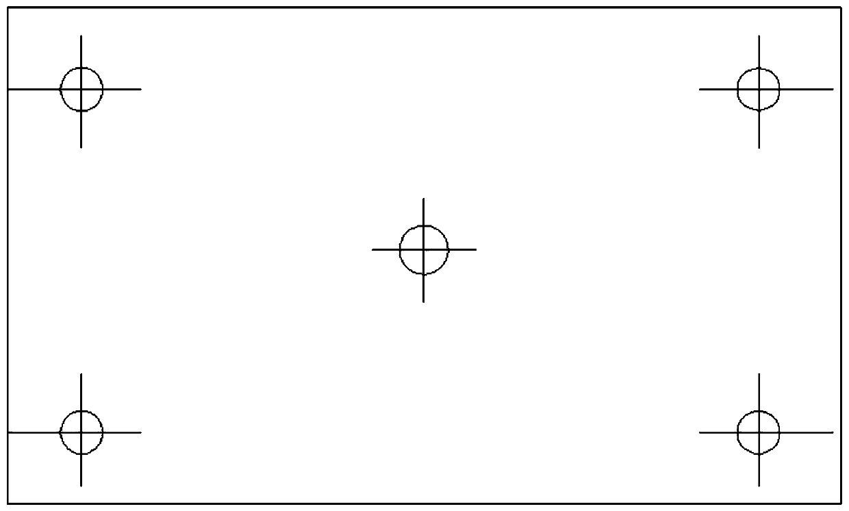
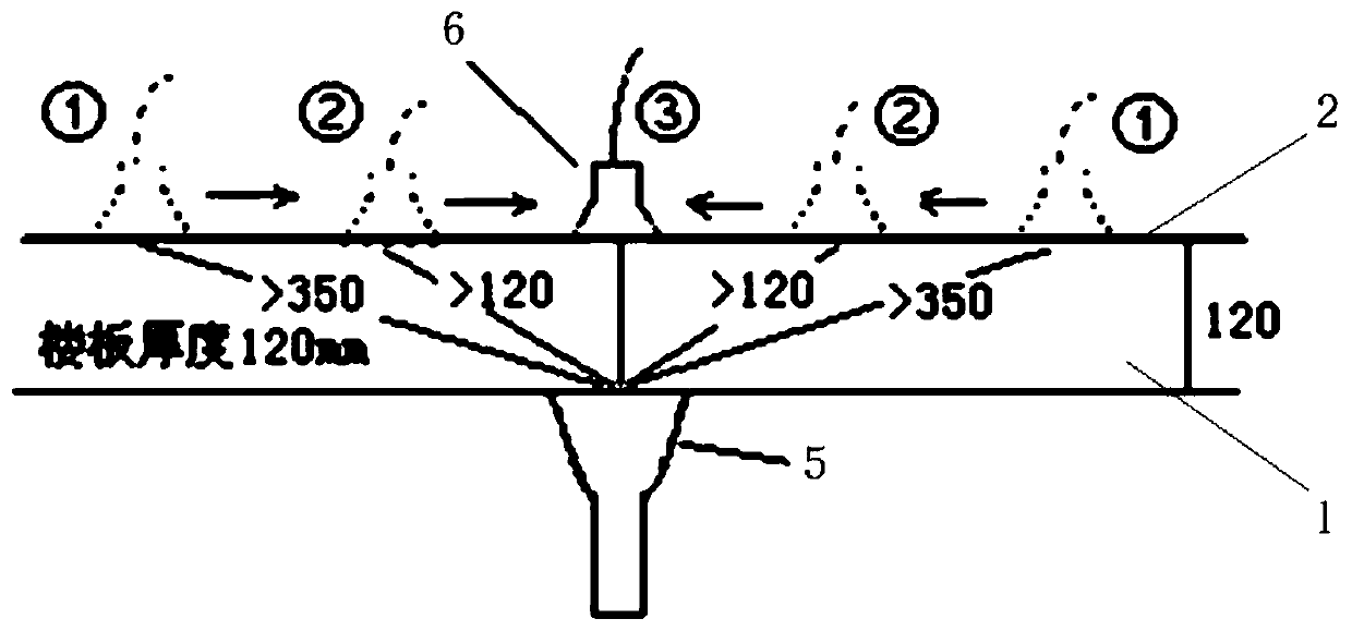
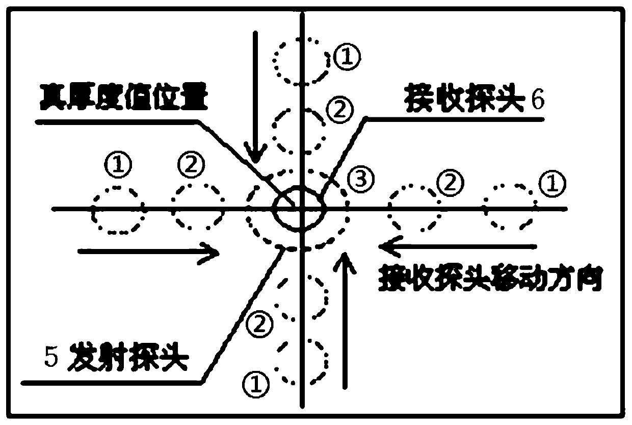
[0023] like Figure 2-3 As shown, the present invention provides a cast-in-place concrete floor thickness detection structure, the detection structure includes a floor to be detected 1, a detection grid 2 is set on the floor to be detected, and the detection grid 2 includes all determined detection points 3 and detection points The nearby detection path 4; the horizontal distance between the detection points 3 is not less than 350mm, the transmitting probe 5 is arranged under the floor 1 to be detected, and the receiving probe 6 is arranged above the floor 1 to be detected, and the transmitting surface of the transmitting probe 5 is larger than that of the receiving probe 6 In this ...


PUM


Abstract

The invention provides a cast-in-place concrete floor thickness detection method which comprises the following steps: determining a detection point, and arranging a detection grid near the detection point; arranging a transmitting probe below one detection point; carrying out mobile scanning on the receiving probe according to the detection grids corresponding to the detection points until the position of the minimum value is found; repeating at the next detection point until all the detection points are detected. The invention further provides a cast-in-place concrete floor thickness detection structure; the selected detection points are determined according to specification requirements, and the detection effectiveness is obviously improved. According to the invention, the detection point grids are arranged, so that the operation orderliness and convenience are improved, the effect of experience in traditional detection can be effectively reduced, and the operability is obviously enhanced. The detection points are arranged normatively, the detection pertinence is high, and the detection precision is high.

Description

technical field [0001] The invention relates to a technology for detecting the thickness of cast-in-situ concrete floor slabs. Background technique [0002] Floor thickness plays a very important role in the safety of engineering structures, and floor thickness inspection is one of the must-check items in engineering quality inspection. Common methods for detecting cast-in-place slabs include: steel tape detection method, level instrument detection method, and electromagnetic principle detection method. The electromagnetic principle detection method is based on electromagnetic wave kinematics, dynamics and modern electronic technology. The floor thickness detector is mainly composed of signal sending, receiving, signal processing, signal indication and other units. It is a simple, convenient and accurate detection method. The error of this method is ±2mm, which is less than the ruler mentioned in the specification. The error of measurement, applied to the acceptance inspec...

Claims


Application Information

Patent Timeline
Patent Type & Authority Applications(China)
IPC IPC(8): G01B7/06
CPCG01B7/10
Inventor 吴晓翠吴为民
Owner 浙江瑞邦科特检测有限公司
Why Eureka
Try Eureka