Manual stamping device

A seal and sliding rod technology, applied in printing, stamping, etc., can solve structural defects, reduce stamping efficiency, troublesome ink filling and other problems, and achieve the effect of avoiding troubles in use and reducing stamping efficiency

Active Publication Date: 2020-05-08
CHONGQING CITY MANAGEMENT COLLEGE
View PDF13 Cites 7 Cited by
  • Summary
  • Abstract
  • Description
  • Claims
  • Application Information

AI Technical Summary

Problems solved by technology

[0004] The purpose of the present invention is to provide a manual stamping device, which is used to solve the trouble of inking caused by the structural defects of the existing stamping device, and reduce the cost of stamping. The problem of chapter efficiency

Method used


Image

  • Manual stamping device
  • Manual stamping device
  • Manual stamping device

Examples


Embodiment Construction

[0042] The present invention will be described in detail below in conjunction with the drawings and specific embodiments. It should be noted that in the drawings or descriptions, similar or identical parts use the same figure numbers, and implementations that are not shown or described in the drawings The method is a form known to those of ordinary skill in the art. In addition, the directional terms mentioned in the embodiments, such as "upper", "lower", "top", "bottom", "left", "right", "front", "rear", etc., are only for reference to the accompanying drawings. The directions are not intended to limit the protection scope of the present invention.

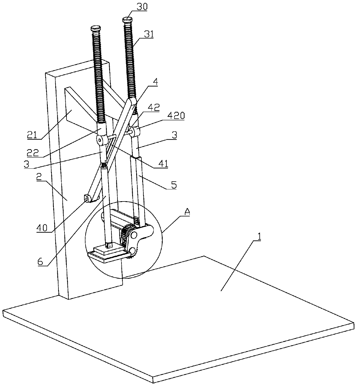
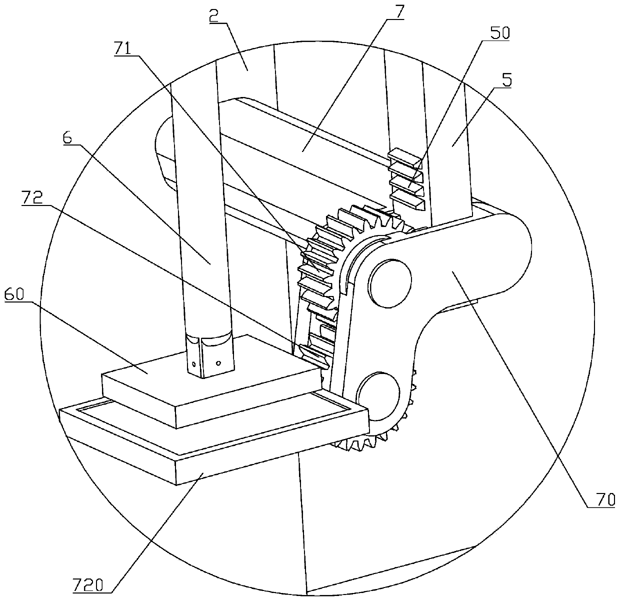
[0043] like Figure 1 to Figure 14As shown, a manual stamping device of the present invention includes a base 1, a vertical plate 2 is fixedly installed on the base 1, two supporting plates 21 are installed horizontally on the upper part of the vertical plate 2, and a sleeve is fixedly installed on the free end of the supporting...


PUM


Abstract

The invention belongs to the technical field of office equipment, and particularly relates to a manual stamping device. The stamping device comprises a base, a vertical plate is fixedly installed on the base, two supporting plates are transversely installed on the upper portion of the vertical plate, sleeves are fixedly installed at the free ends of the supporting plates, lifting rods are arrangedin the sleeves in a penetrating mode, limiting tables are installed at the top ends of the lifting rods, and a fixing column is fixedly installed on the vertical plate. A mounting seat is verticallyinstalled at the free end of the fixing column, a sliding rod is arranged in the mounting seat in a penetrating mode, a first gear and a second gear which are engaged with each other are installed inthe mounting seat, the first gear corresponds to racks, circular truncated cones are integrally formed on the side walls of the two sides of the first gear, and notches are formed in the circular truncated cones; clamping strips are vertically arranged in the notches at the lower end of the sliding rod, and the clamping strips are located under the racks; and an inkpad table is horizontally installed on the side, close to a connecting rod, of the second gear, a seal is arranged at the lower end of the connecting rod, and the seal is located above the inkpad table. The manual stamping device aims to solve the problems that inking is troublesome and stamping efficiency is reduced due to structural defects of an existing stamping device.

Description

technical field [0001] The invention belongs to the technical field of office equipment, and in particular relates to a manual stamping device. Background technique [0002] Chinese invention patent (publication number: CN104527243B) discloses a simple manual stamping machine, including a support, which is characterized in that the support is provided with two vertical chute symmetrically arranged, and a stopper is installed in the support The two sides of the block are respectively hinged with the sliding block, and the two sliding blocks are installed in sliding fit with the vertical chute respectively, and the two sliding blocks are respectively supported by springs installed on the chute; the upper and lower sides of the block The two ends are respectively hinged with the connecting rods, and the other ends of the two connecting rods are respectively hinged with the upper and lower ends of the swing rod, so that the swing rod, the upper and lower connecting rods and the ...

Claims


Application Information

Patent Timeline
Patent Type & Authority Applications(China)
IPC IPC(8): B41K3/56B41K3/04
CPCB41K3/56B41K3/04
Inventor 余志涵
Owner CHONGQING CITY MANAGEMENT COLLEGE
Why Eureka
Try Eureka