
An automatic unloader for hot melt adhesive film production

A hot-melt adhesive film and automatic unloading technology, which is applied in the direction of conveyor objects, transportation and packaging, etc., can solve the problems of labor cost, time consumption, and low work efficiency, so as to achieve high work efficiency and avoid sagging deformation , to avoid the effect of moving

Active Publication Date: 2021-06-15
东莞市赛普机电设备有限公司
View PDF6 Cites 0 Cited by
  • Summary
  • Abstract
  • Description
  • Claims
  • Application Information

AI Technical Summary

Problems solved by technology

[0004] In order to overcome the need for two or more workers to unload it, this process needs to consume more time, the work efficiency is low, and the shortcomings of labor costs are relatively expensive. The technical problem to be solved is: to provide a work efficiency High, automatic unloading machine for hot melt adhesive film production that can save labor costs

Method used


Image

  • An automatic unloader for hot melt adhesive film production
  • An automatic unloader for hot melt adhesive film production
  • An automatic unloader for hot melt adhesive film production

Examples


Embodiment 1

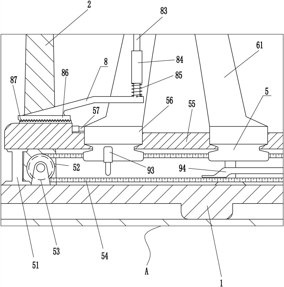
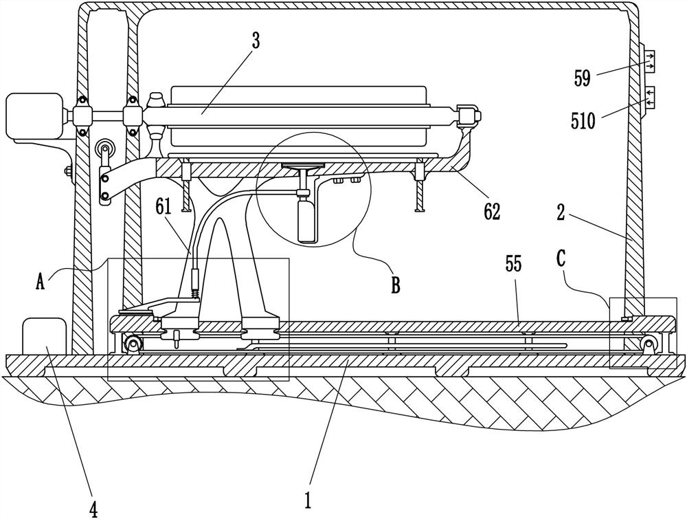
[0029] An automatic unloading machine for hot melt adhesive film production, such as Figure 1-6 As shown, it includes a base 1, a frame 2, a moving mechanism 5 and a push-out mechanism 6. A frame 2 and a moving mechanism 5 are installed on the top of the base 1. The frame 2 is located at the rear side of the moving mechanism 5, and the moving mechanism 5 is provided with a pushing Mechanism 6, the push-out mechanism 6 is used to push out the rolled hot-melt adhesive film, and the moving mechanism 5 is used to drive the push-out mechanism 6 to move laterally.

[0030] It also includes a control module, and the moving mechanism 5 and the control module are electrically connected.

[0031] The moving mechanism 5 includes a pillar 51, a drum 52, a servo motor 53, a synchronous belt 54, a slide rail 55, a slider 56, a first travel switch 57, a second travel switch 58, a right shift key 59 and a left shift key 510, and a base 1 The top is fixedly connected with a servo motor 53 an...

Embodiment 2

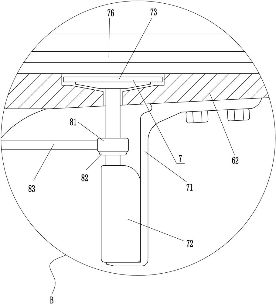
[0037] On the basis of Example 1, such as figure 2 , image 3 , Figure 4 , Image 6 , Figure 7 with Figure 8 As shown, a support mechanism 7 is also included, and the support mechanism 7 includes a mounting base 71, a first electric push rod 72, a pressure sensor 73, a guide sleeve 74, a guide rod 75 and a push plate 76, and the middle of the bottom of the horizontal plate 62 passes through Mounting seat 71 is equipped with first electric push rod 72, and first electric push rod 72 passes through cross plate 62, and pressure sensor 73 is installed on the telescoping rod top of first electric push rod 72, and cross plate 62 left and right parts are all embedded The guide sleeve 74 is installed in the guide sleeve 74, and the sliding type is provided with a guide rod 75 in the guide sleeve 74, and the top of the guide rod 75 is affixed with a push plate 76.

[0038] Also include positioning mechanism 8, positioning mechanism 8 includes slip ring 81, baffle plate 82, con...


PUM


Abstract

The invention relates to an automatic unloader, in particular to an automatic unloader for hot melt adhesive film production. The technical problem to be solved is how to provide an automatic unloader for hot melt adhesive film production with high working efficiency and saving labor costs. The utility model relates to an automatic unloader for hot melt adhesive film production, which includes a base, a frame, a moving mechanism, a pushing mechanism, etc.; The present invention can drive the push-out mechanism to move to the right through the moving mechanism, and the push-out mechanism can push out the hot-melt adhesive film on the automatic winding roller, which can replace manual operation, has high work efficiency, and can operate the equipment by one staff member. , so that labor costs can be saved, and the hot-melt adhesive film can be supported by the supporting mechanism to prevent the hot-melt adhesive film from falling directly onto the horizontal plate after being pushed out, thereby avoiding damage to the hot-melt adhesive film.

Description

technical field [0001] The invention relates to an automatic unloading machine, in particular to an automatic unloading machine for hot melt adhesive film production. Background technique [0002] Hot melt adhesive film is a film product with or without release paper, which can be conveniently operated continuously or intermittently. It is widely used in various fabrics, paper and metal bonding, hot melt adhesives After the film is produced, it generally requires two or more workers to unload it, and then push out the rod for winding the hot melt adhesive film. This process takes a lot of time, is inefficient, and consumes Labor costs. [0003] Therefore, it is necessary to develop a device with high work efficiency and can save labor costs to solve the existing problems. Contents of the invention [0004] In order to overcome the need for two or more workers to unload it, this process needs to consume more time, the work efficiency is low, and the shortcomings of labor ...

Claims


Application Information

Patent Timeline
Patent Type & Authority Patents(China)
IPC IPC(8): B65G47/82
CPCB65G47/82
Inventor 吴光祥
Owner 东莞市赛普机电设备有限公司
Learn More