
Massage machine

A technology of driving mechanism and lifting mechanism, applied in pneumatic massage, vibration massage, kneading massage appliances, etc., can solve the problems of inability to give and limited movement changes.

Active Publication Date: 2020-05-05
FUJI MEDICAL INSTR MFG
View PDF8 Cites 0 Cited by
  • Summary
  • Abstract
  • Description
  • Claims
  • Application Information

AI Technical Summary

Problems solved by technology

However, since the action of the treatment piece is the same as that of the usual kneading and pressing massage, the variation of the action is limited, and the movement of the treatment piece cannot be smaller than the orbit of kneading and pressing. changing massage
[0006] In addition, since the movement of the treatment element is greater than that of human fingers, it is impossible to provide a stimulation close to that of a massage that is narrower than that of a normal kneading massage.

Method used


Image

  • Massage machine
  • Massage machine
  • Massage machine

Examples


no. 1 approach

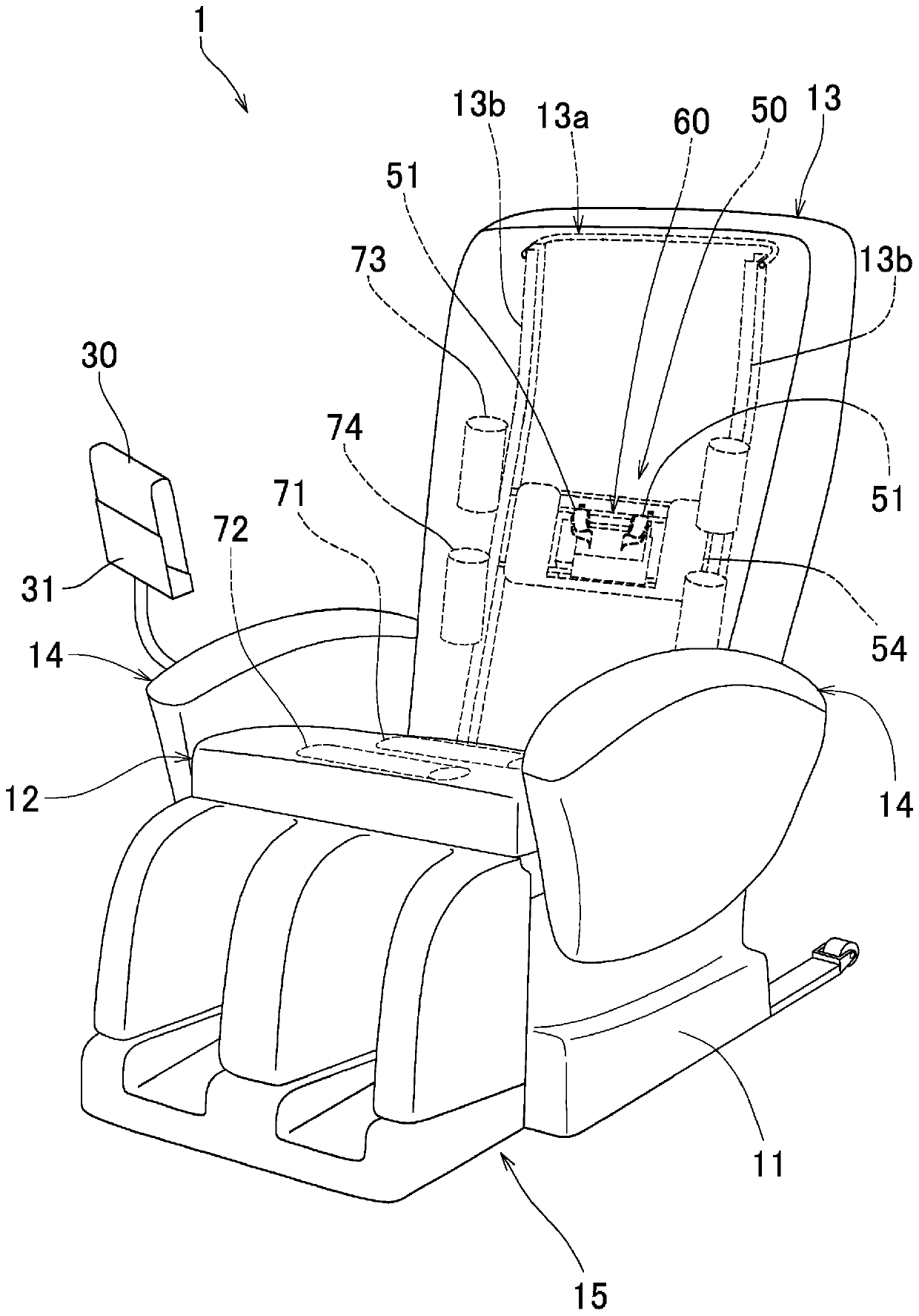
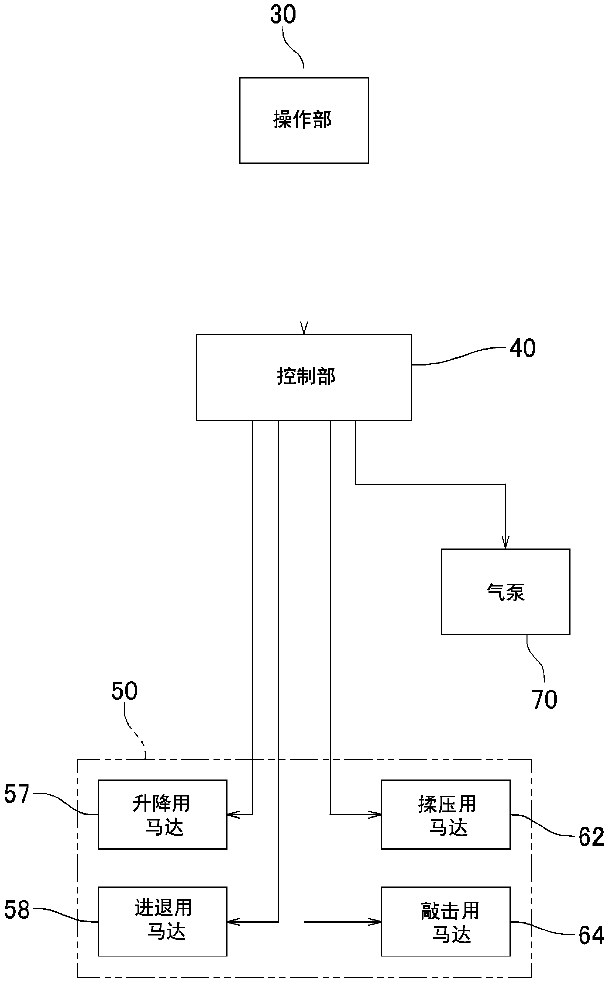
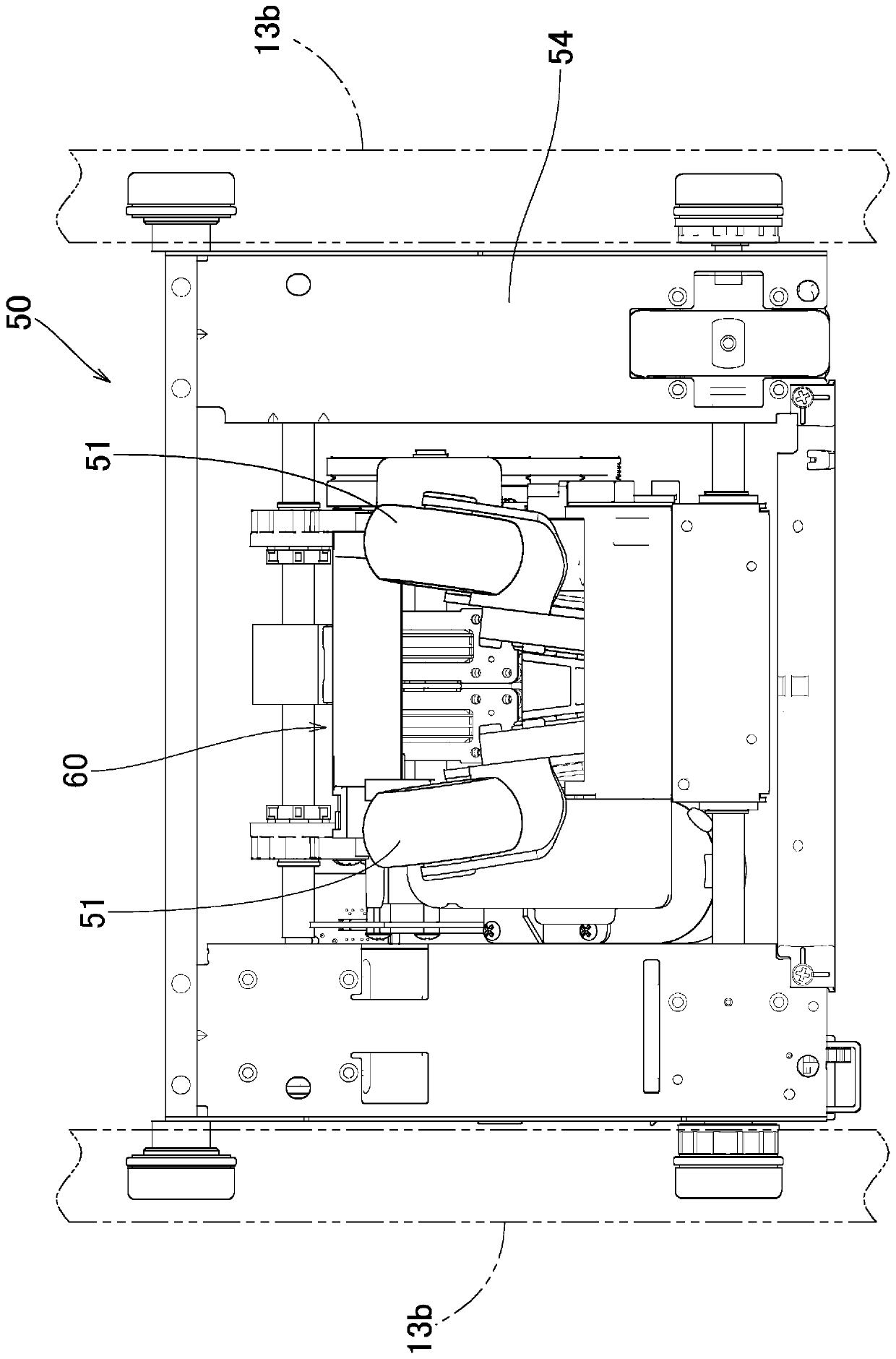
[0029] Below, based on Figure 1 to Figure 12 A massage machine according to a first embodiment of the present invention will be described. In this embodiment, an example of a so-called chair-type massage machine that performs a massage while supporting a sitting user will be described.

[0030] Such as figure 1 As shown, the massage machine 1 of this embodiment is provided with: a base portion 11, which is placed on the ground and supports the entire chair stably; a seat portion 12, which supports the user's buttocks above the base portion 11; a backrest part 13, which supports the back of the user on the rear side of the seat part 12; armrest part 14, which supports the user's elbow and forearm part on the left and right sides of the seat part 12; The side supports the user's feet; the operation unit 30 receives various operation inputs related to the massage from the user; and the control unit 40 controls the operating states of the mounted plurality of massage mechanisms...

no. 2 approach

[0077] In the massage machine according to the first embodiment, the control unit 40 is configured so that the position in the front-rear direction on the trajectory of the reference trajectory is used as a part of the predetermined section near the front of the user, specifically, the position on the trajectory of the reference trajectory is used. front and rear direction ( Figure 10 in front of the z-axis direction) and on the outside of the body (in the Figure 10 In the case of the shown reference trajectory, the partial interval A on the lower side in the xy plane is used as a local movement range in which the treatment member 51 is relatively reciprocated by the kneading and pressing mechanism of the drive mechanism part 60, and the application area is relatively increased. The amount of movement in the left and right direction of the treatment member 51, but not limited thereto. For example, as a second embodiment, such as Figure 13 , Figure 14 As shown, it is als...

no. 3 approach

[0081]In the massage machine according to the first embodiment, the control unit 40 exclusively uses a part of the predetermined section in the reference trajectory whose position in the front-rear direction is close to the front of the user as the kneading mechanism of the drive mechanism unit 60. The local movement range of the relative reciprocating movement of the treatment element 51 is not limited thereto. For example, as a third embodiment, such as Figure 15 As shown, the control unit 40 can also select a part of the predetermined interval including the frontmost position closest to the user side in the reference trajectory as the state in which the driving mechanism unit 60 makes the treatment member 51 perform relative reciprocating movement, and The state of selecting a part of the predetermined section including the rearmost position farthest from the user side in the reference trajectory is selected as the movement range in which the treatment element 51 is relati...


PUM


Abstract

The invention provides a massage machine. Under the control of a controller, a drive mechanism portion moves a massaging member and an ascent-descent mechanism moves up and down the massaging member together with the entire drive mechanism portion. During an ordinary kneading massage, the massaging member performs a relative motion to describe a reference locus in the shape of a closed curve. Thecontroller controls to make the massaging member perform a relative reciprocating movement within a partial movement range corresponding to a partial segment of the reference locus and simultaneouslycontrols to make the ascent-descent mechanism move the drive mechanism portion up and down. The relative reciprocating movement of the massaging member along the partial segment of the reference locusand the up-down movement of the entire drive mechanism portion are combined together to produce a new motion of the massaging member describing a locus different from the reference locus. The actionof the massaging member is applied to a narrow range and a new stimulus is given.

Description

[0001] This application claims priority to Patent Application No. 2018-201047 filed in Japan on October 25, 2018, the entire contents of which are hereby incorporated by reference. technical field [0002] The present invention relates to a massage machine for performing massage such as kneading pressure on a user by operating a treatment member while the user's body is supported by a backrest. Background technique [0003] A massage machine (for example, a chair-type massage machine) that performs massage while supporting the user's body has a structure in which a treatment member installed on the backrest as a massage mechanism is positioned up and down according to the user's physique, The member repeatedly moves relative to the user who relies on the backrest, thereby performing massage such as kneading and tapping on the user. [0004] Among such massage machines, there is a massage machine that not only operates the driving mechanism of the treatment member so that the...

Claims


Application Information

Patent Timeline
Patent Type & Authority Applications(China)
IPC IPC(8): A61H7/00A61H9/00A61H23/00A61H23/02
CPCA61H7/007A61H9/0078A61H23/006A61H23/02A61H2201/0149A61H2201/1215A61H2205/06A61H2205/065A61H1/00A61H2201/5007A61H2201/0103A61H2203/0431A61H2201/0192A61H2205/081A61H2201/1623A61H2201/5043A61H2201/5035A61H2201/1669A61H2205/086A61H9/0057A61H2201/1633A61H2205/088A61H2201/1661A61H2201/1676
Inventor 花田吏吉田敏久
Owner FUJI MEDICAL INSTR MFG
Learn More