
Movable textile frame damping device

A technology of shock absorbing device and textile frame, applied in the field of textile machinery, can solve the problems of inconvenience of moving and transporting the frame, reducing the service life of the frame, vibration of the textile frame, etc. safety effect

Inactive Publication Date: 2020-05-01
王冬
View PDF0 Cites 3 Cited by
  • Summary
  • Abstract
  • Description
  • Claims
  • Application Information

AI Technical Summary

Problems solved by technology

Textile machine is the full name of the tool that processes thread, silk, hemp and other raw materials into silk thread and then weaves it into cloth, such as spinning pendant, spinning wheel, spindle, pedal loom, modern mechanical loom, modern numerical control automatic loom, etc. , at present, the textile machine plays an important role in the textile industry, and the textile frame is a foundation of the textile machine. Whether the textile frame is good or not determines the working efficiency of a textile machine. The existing textile machine frame extends downward To the ground, the frame as a whole is fixed, and there are no rollers on the frame, so it is very inconvenient to move and carry the frame, which brings inconvenience to users; in addition, when the textile machine is working, the textile frame will vibrate, resulting in loose, reducing the life of the rack

Method used


Image

  • Movable textile frame damping device
  • Movable textile frame damping device
  • Movable textile frame damping device

Examples

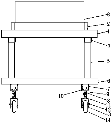

Embodiment Construction

[0023] The following will clearly and completely describe the technical solutions in the embodiments of the present invention with reference to the accompanying drawings in the embodiments of the present invention. Obviously, the described embodiments are only some, not all, embodiments of the present invention. Based on the embodiments of the present invention, all other embodiments obtained by persons of ordinary skill in the art without making creative efforts belong to the protection scope of the present invention.

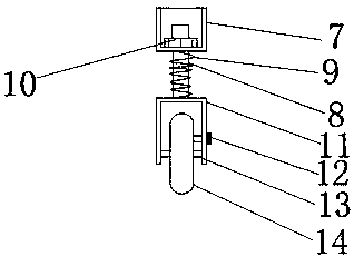
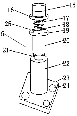
[0024] see Figure 1-3 , the present invention provides a technical solution:

[0025] A movable shock absorber for a textile frame, comprising a base 6 and a frame bearing platform 1, the top right side of the base 6 is threadedly connected with a shock absorber 5, through which the shock absorber 5 generated during the working process of the textile machine 3 can be The vibration of the vibration is offset by the damping effect of the damping rod 5, prolong...


PUM


Abstract

The invention relates to the technical field of textile machineries, in particular to a movable textile frame damping device. The movable textile frame damping device comprises a base and a frame bearing platform; a damping rod is connected with the right side of the top end of the base in a threaded mode, a baffle is arranged at the top end of the frame bearing platform, a textile machine is placed in the inner side of the baffle, a cylindrical sleeve is arranged on the right side of the bottom end of the frame bearing platform, the base is connected with the frame bearing platform through the damping rod, a U-shaped connecting plate is arranged on the right side of the bottom end of the base, a support rod is connected with the center of the lower side of the U-shaped connecting plate ina sleeved mode, the support rod is fixed to the U-shaped connecting plate by bolts, a damping spring is connected with the outer wall of the support rod in a sleeved mode, a U-shaped mounting plate is welded to the lower side of the support rod, a crossbar is fixedly connected with the lower side of the U-shaped mounting plate, the crossbar is fixedly connected with a mobile wheel in a sleeved mode, and a brake inserting rod is arranged on the upper side of the crossbar; and overall equipment is convenient to move, the damping effect is good, the safety is high, and the movable textile framedamping device is worth popularizing.

Description

technical field [0001] The invention relates to the technical field of textile machinery, in particular to a movable textile frame damping device. Background technique [0002] Textile machines are also called textile machines, looms, cotton spinning machines, etc. The ancient textile machines were looms driven by human power. Textile machine is the full name of the tool that processes thread, silk, hemp and other raw materials into silk thread and then weaves it into cloth, such as spinning pendant, spinning wheel, spindle, pedal loom, modern mechanical loom, modern numerical control automatic loom, etc. , at present, the textile machine plays an important role in the textile industry, and the textile frame is a foundation of the textile machine. Whether the textile frame is good or not determines the working efficiency of a textile machine. The existing textile machine frame extends downward To the ground, the frame as a whole is fixed, and there are no rollers on the fra...

Claims


Application Information

Patent Timeline
Patent Type & Authority Applications(China)
IPC IPC(8): F16F15/04
CPCF16F15/04
Inventor 王冬
Owner 王冬
Learn More