Eureka AIR delivers breakthrough ideas for toughest innovation challenges, trusted by R&D personnel around the world.

Psychological health state eye-movement feedback device

A technology of mental health and feedback devices, applied in psychology devices, medical science, sensors, etc., can solve the problems of reducing the feedback quality of desktop eye trackers, easy to follow the eye to swing, lack of fixed structure, etc., and achieve good accuracy , The effect of distance adjustment is convenient and the quality of feedback is improved

Inactive Publication Date: 2020-05-01
JILIN TEACHERS INST OF ENG & TECH
View PDF10 Cites 0 Cited by
  • Summary
  • Abstract
  • Description
  • Claims
  • Application Information

AI Technical Summary

Problems solved by technology

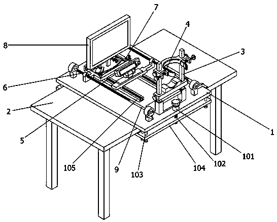
[0005] In order to solve the above-mentioned technical problems, the present invention provides a mental health state eye movement feedback device to solve the following deficiencies in the actual use of the existing desktop eye tracker, such as: 1. The existing desktop eye movement The instrument is mainly divided into three parts: the main body of the eye tracker, the head support mechanism and the computer display screen. The distance between the three parts needs to be adjusted before the desktop eye tracker is used. However, the existing desktop eye tracker In the eye tracker, the main body of the eye tracker and the computer display screen are placed randomly, so it is very inconvenient to adjust, and it has to be adjusted again when it is transported to another workbench; 2. The existing desktop eye tracker Although the head support mechanism in the instrument can support the head, due to the lack of an effective fixed structure, the head of the measured person is easy to swing with the eyes during detection, thereby reducing the feedback quality of the desktop eye tracker The problem

Method used


Image

  • Psychological health state eye-movement feedback device
  • Psychological health state eye-movement feedback device
  • Psychological health state eye-movement feedback device

Examples


Embodiment

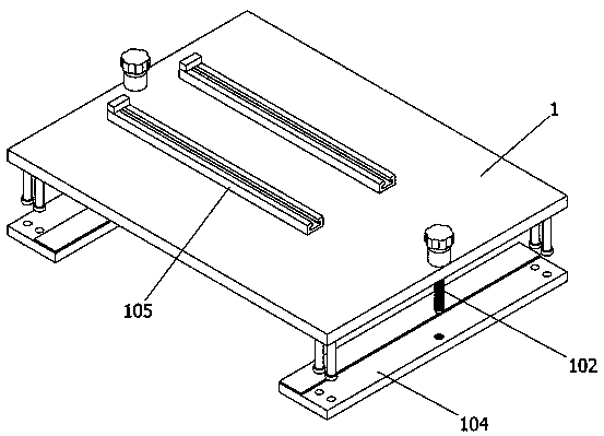
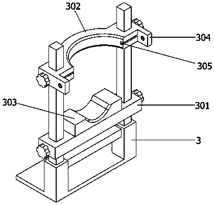
[0032] as attached figure 1 To attach Figure 8 Shown:

[0033] The present invention provides a mental health state eye movement feedback device, which includes: a fixed plate 1, which is fixedly installed on the upper part of the workbench 2, and the fixed plate 1 also includes a shaft sleeve 101, a first threaded rod 102, and a limit sliding column 103, the clamping plate 104 and the sliding track 105, the upper end of the fixed plate 1 is provided with a shaft sleeve 101 on both sides of the front and back, and the inside of each shaft sleeve 101 is connected with the first threaded rod 102 that runs through the fixed plate 1, fixed Two limit sliding posts 103 are provided at the four corners of the bottom end surface of the plate 1, and a clamping plate 104 is slidably connected to the four limit sliding posts 103 on the front side and the four limit sliding posts 103 on the rear side. , each clamping plate 104 is provided with a threaded through hole in the middle of t...


PUM


Abstract

The invention provides a psychological health state eye-movement feedback device. The device comprises: a fixing plate, the fixing plate is fixedly mounted on the upper part of a workbench, the fixingplate still includes axle sleeves, first threaded rods, spacing sliding columns, clamping plates and sliding rails. According to the invention, a cranking bar on a right-side driving mechanism is manually rotated to make a first threaded cylinder drive an eye tracker main body to move forward and backward through a sliding seat under the action of threads, then a cranking bar on a left-side driving mechanism is manually rotated to make a second threaded cylinder drive a computer display screen to move forward and backward through a mounting seat under the action of threads, after the adjustment is finished, the rotations of the two driving mechanisms are stopped, and the two driving mechanisms are respectively in threaded connection with the first threaded cylinder and the second threadedcylinder, so that the adjustment of the distance between the eye tracker main body and the computer display screen is more convenient, the accuracy is better, and the reliability of the desktop typeeye tracker during adjustment is improved.

Description

technical field [0001] The invention belongs to the technical field of eye movement feedback devices, and more specifically relates to an eye movement feedback device for mental health status. Background technique [0002] The eye tracker is an important instrument for the basic research of psychology. Eye trackers are used to record the characteristics of eye movement tracks when people process visual information, and are widely used in the research of attention, visual perception, reading and other fields. As early as the 19th century, some people studied human psychological activities by examining human eye movements, and explored the relationship between eye movements and human psychological activities by analyzing recorded eye movement data. The advent of the eye tracker provides psychologists with the use of eye movement technology (eye movement technique) to explore the visual information processing mechanism of people under various conditions, and to observe its dir...

Claims


Application Information

Patent Timeline
IPC IPC(8): A61B5/16
CPCA61B5/163A61B5/165
Inventor 王斐孙焱陈春芳韩杨
Owner JILIN TEACHERS INST OF ENG & TECH
Why Eureka
Eureka Blog
Learn More