Combined automatic seed supply device of large-grain-size plot seeder
A seed supply device and seeder technology, which is applied in the directions of seeder parts, etc., can solve the problems of slow seed supply by manual labor, manual seed replacement after downtime, and achieve the effects of reducing quantity, improving work efficiency, and reducing seeding cost.
- Summary
- Abstract
- Description
- Claims
- Application Information
AI Technical Summary
Problems solved by technology
Method used
Image
Examples
Embodiment 1
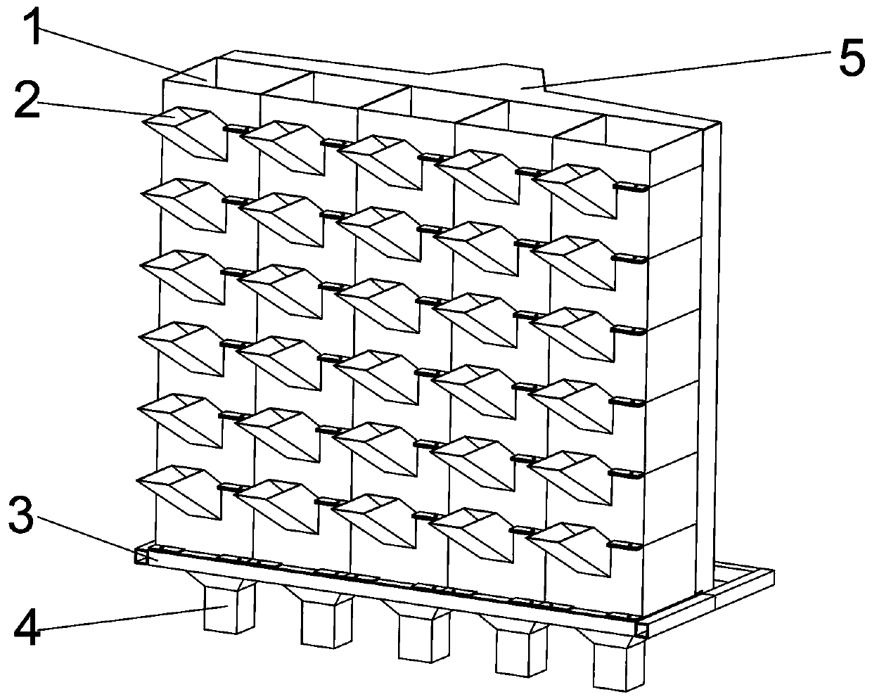
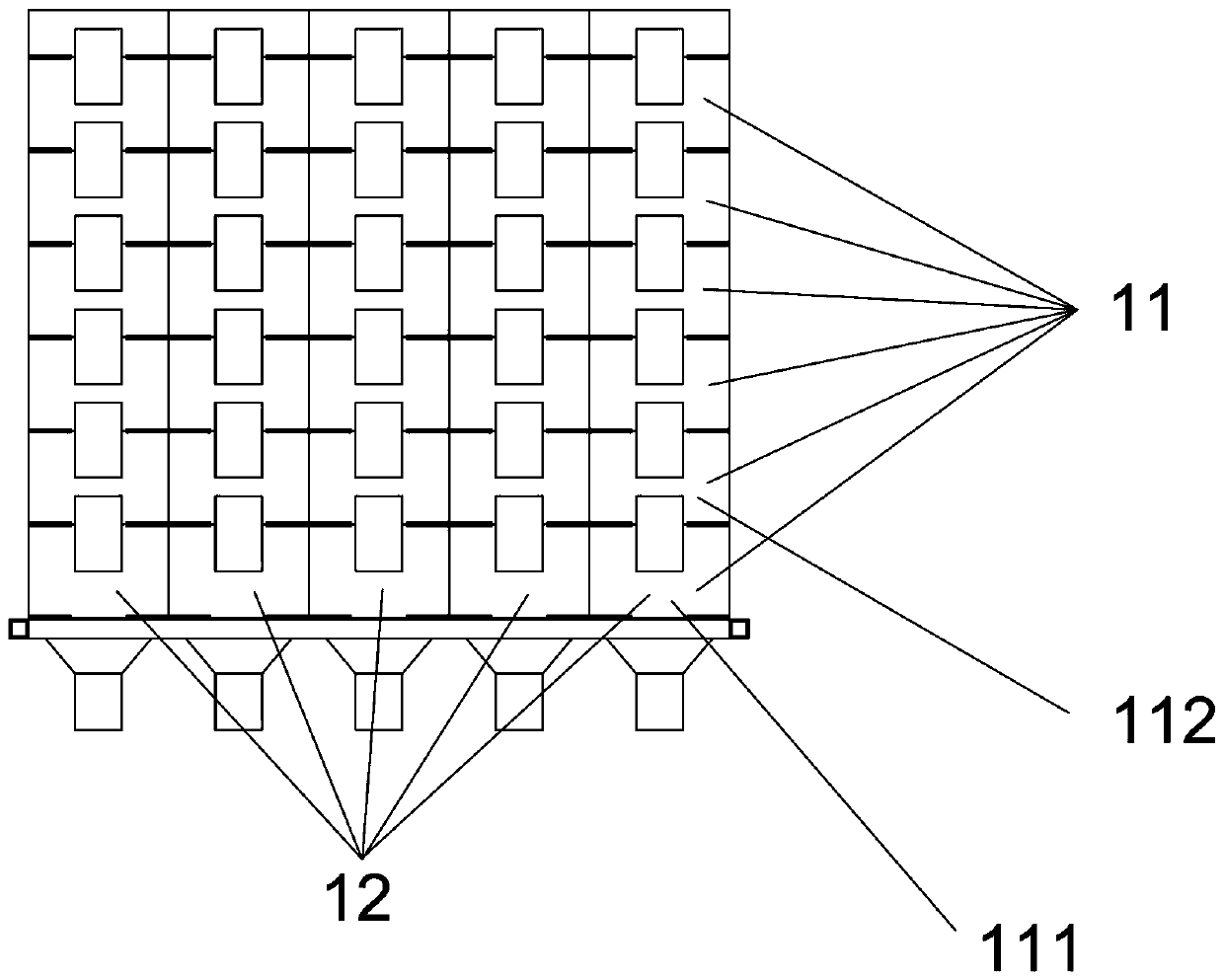
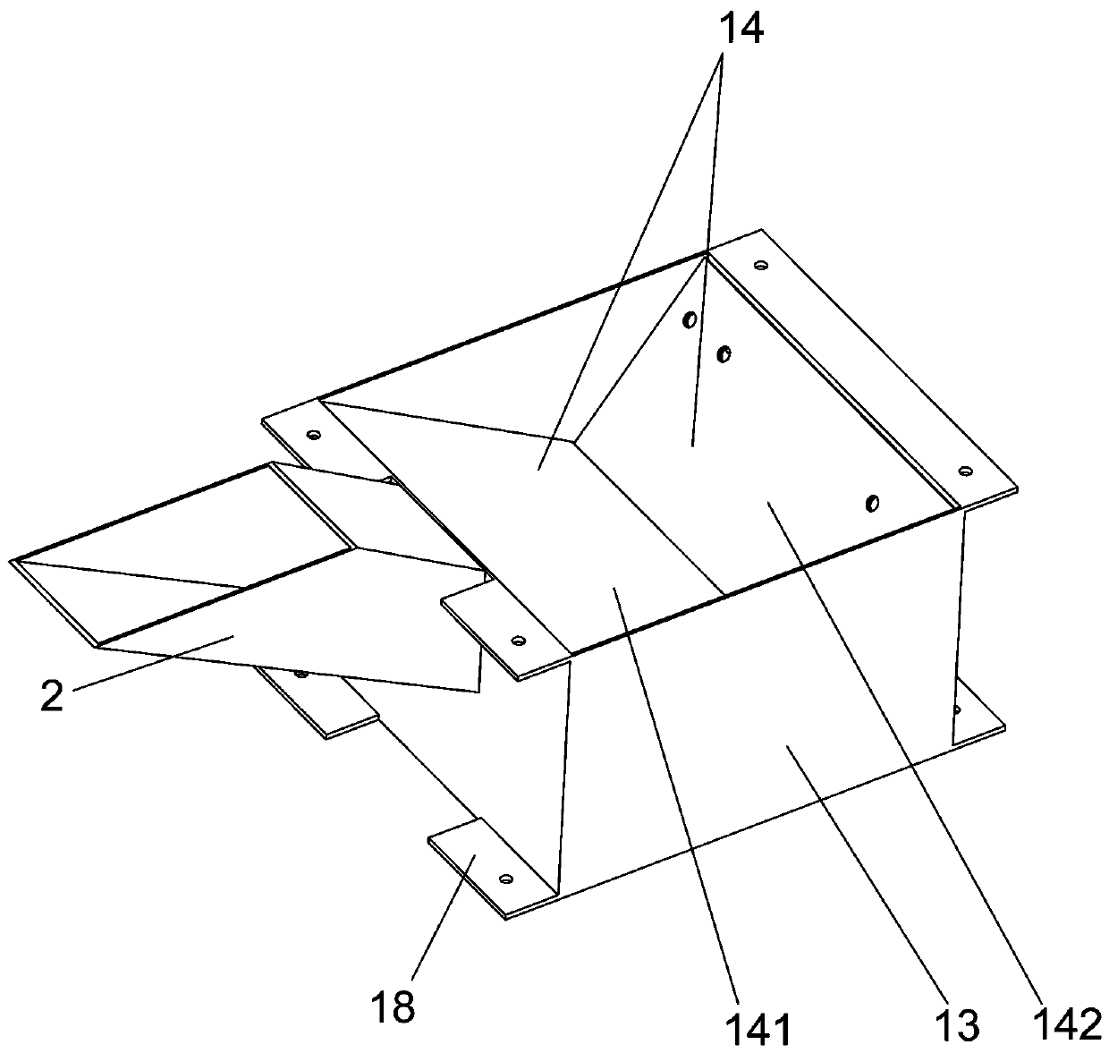
[0029] This embodiment provides a combined automatic seed supply device for a large particle size community seeder, such as figure 1 , figure 2 As shown, it includes a mounting frame 3, a seed storage unit and a control unit 5; the seed storage mechanism includes a seed box unit 1 and a feeding unit 2, and the seed box unit 1 is provided with a feeding unit 2; 6 seed box units 1 from the bottom Upstairs, the vertical box group 11 is connected in series and connected vertically, and the five seed box units 1 are arranged side by side and independent of each other to form a horizontal box group 12. As shown in Fig. xx, the seed box unit 1 includes hollow upper and lower The housing 13 of the mouth, the upper and lower ends of the front and rear side walls of the housing 13 are welded and fixed with a connecting platform 18, the upper end surface of the connecting platform 18 on the upper end of the housing 11 is flush with the upper end surface of the housing 11, and the lower ...
Embodiment 2
[0038] The difference between embodiment 2 and embodiment 1 lies in that a wheel groove is formed on the circumferential side of the runner along the circumference.
[0039] Such as Figure 8 As shown, the middle part of the circumference side of the runner 541 has a wheel groove 58 along the circumference, and the traction rope fixing column 545 is fixed in the wheel groove 58. When the runner 541 rotates, the traction rope 6 fixed on the traction rope fixing column 545 will Following the rotation of the runner 541, it is wound in the wheel groove 58 on the peripheral side wall of the runner 541. In Embodiment 1, the traction rope 6 is directly wound on the peripheral side wall of the runner 541. Since the peripheral side wall of the runner 541 is smooth, Therefore, unwinding phenomenon is easy to occur, and when the device of this embodiment is in use, the traction rope is wound 6 in the wheel groove 58 on the circumferential side wall of the runner 541, and due to the limit...
PUM
 Abstract
Description
Claims
Application Information
 - R&D
- Intellectual Property
- Life Sciences
- Materials
- Tech Scout
- Unparalleled Data Quality
- Higher Quality Content
- 60% Fewer Hallucinations
Browse by: Latest US Patents, China's latest patents, Technical Efficacy Thesaurus, Application Domain, Technology Topic, Popular Technical Reports.
© 2025 PatSnap. All rights reserved.Legal|Privacy policy|Modern Slavery Act Transparency Statement|Sitemap|About US| Contact US: help@patsnap.com


