Connecting valve facilitating vacuum pumping and vacuum breaking

A technology for connecting valves and breaking vacuum, which is applied in the direction of lifting valves, valve details, valve devices, etc., can solve the problems of not being able to break the vacuum of the suction cup, restrict the direction of ventilation, and not suitable for applications, etc., to achieve convenient implementation, reduce energy consumption, and structure compact effect

Pending Publication Date: 2020-04-28
广东创智智能装备有限公司
View PDF0 Cites 0 Cited by
  • Summary
  • Abstract
  • Description
  • Claims
  • Application Information

AI Technical Summary

Problems solved by technology

[0002] At present, in order to improve the suction force, some suction cups on the market are equipped with a suction one-way valve. After the user closes the suction cup to the adsorbed part, connect the suction pump to the suction one-way valve on the suction cup to close the negative pressure chamber of the suction cup. After the gas is pumped out, the pumping one-way valve is automatically closed, and the adsorption effect is better. However, the pumping one-way valve restricts the ventilation direction, and the air supply from the outside to the existing pumping one-way valve cannot break the vacuum of the suction cup. , if the user wants to separate the suction cup from the adsorbed part, he can only adopt other methods, such as vigorously prying the suction cup with a knife to break the vacuum, or setting other vacuum breaking structures on the suction cup, which is more troublesome to implement and not suitable for some occasions Applications

Method used


Image

  • Connecting valve facilitating vacuum pumping and vacuum breaking
  • Connecting valve facilitating vacuum pumping and vacuum breaking
  • Connecting valve facilitating vacuum pumping and vacuum breaking

Examples


Embodiment 1

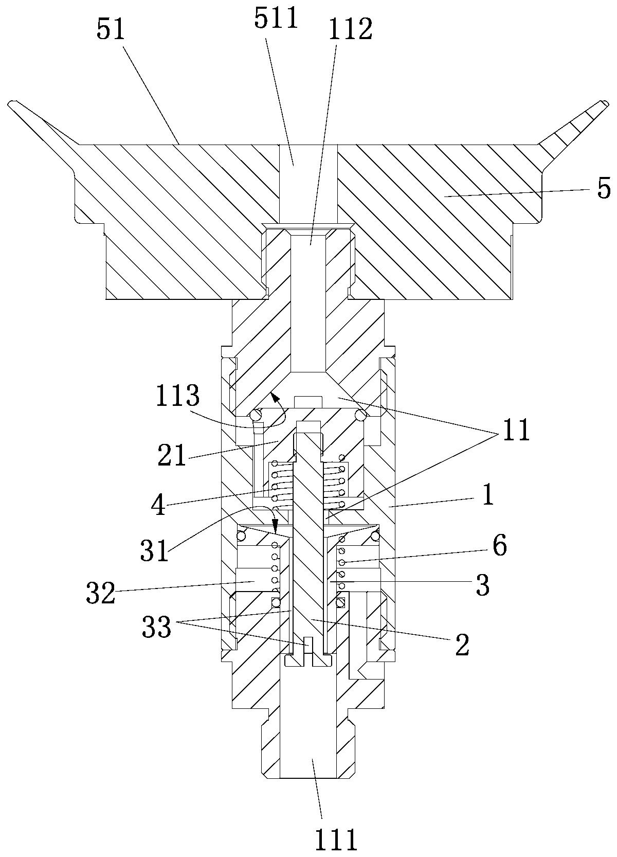
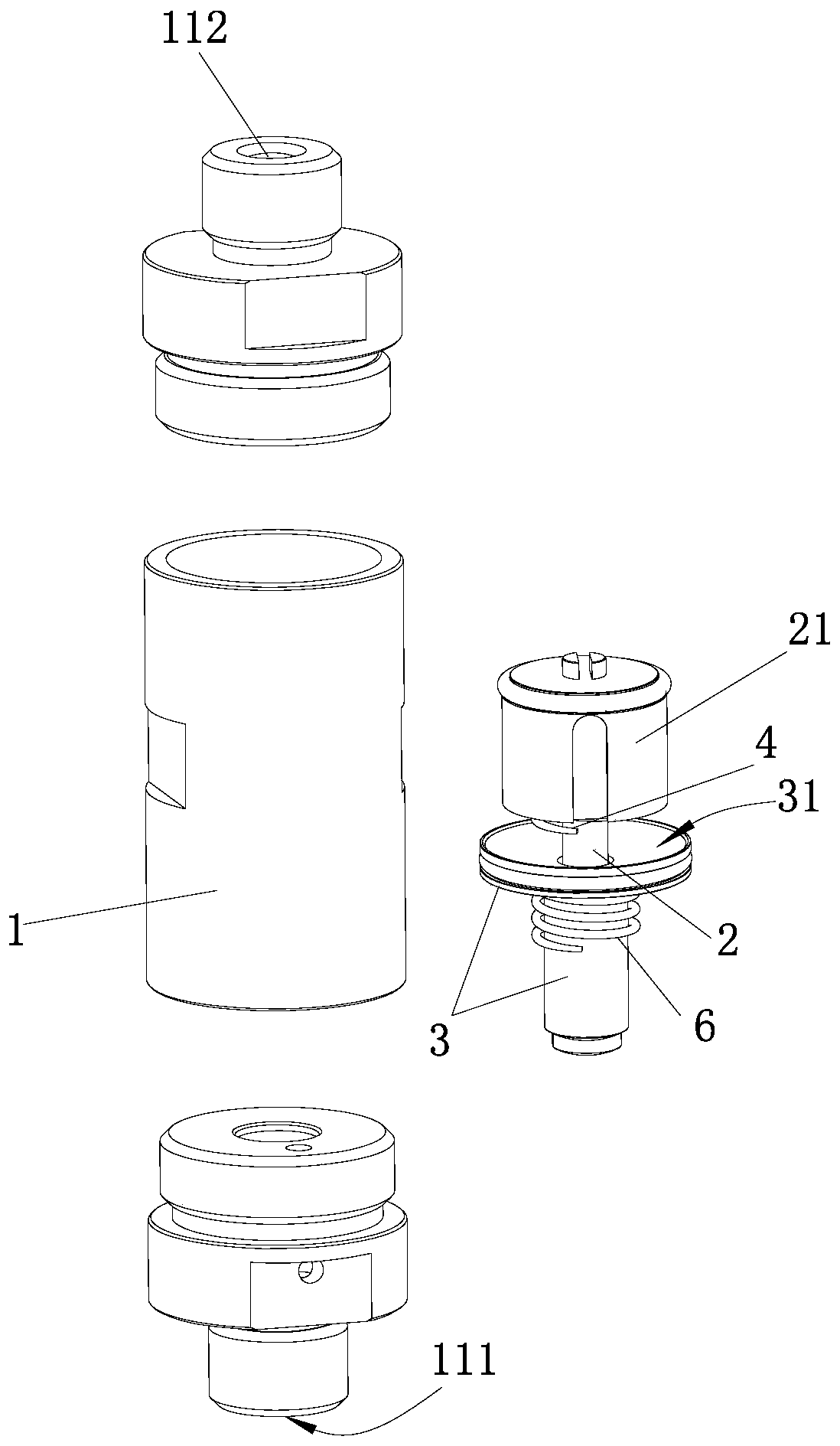
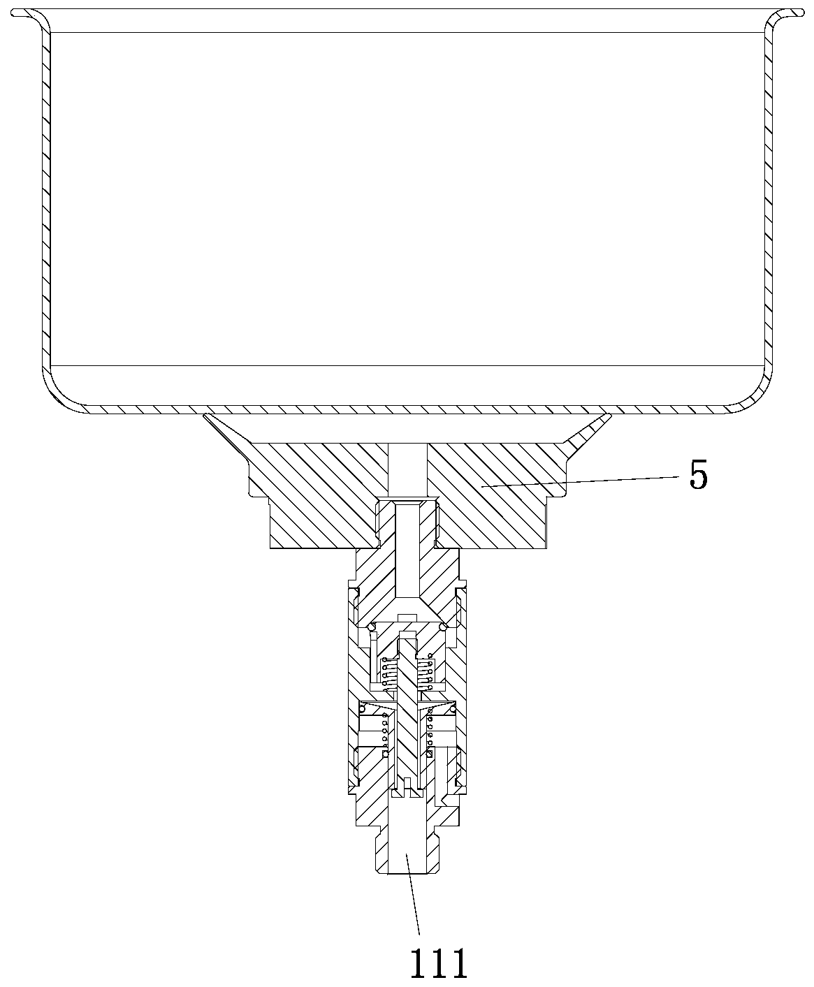
[0028] In Embodiment 1, the air suction port 111 is located on the wall of the connecting valve 1 between the sealing structure and the driving member 3, so that the driving member 3 does not make any contact between the air suction port 111 and the driving member 3. The passage of airflow between the sealing structures forms an obstacle, and the passage of airflow is convenient.

Embodiment 2

[0029]Embodiment 2, the air extraction and delivery port 111, the driving part 3, the sealing structure, and the object connection port 112 are set in sequence, and the driving part 3 is set on the movable part at the end close to the air extraction and delivery port 111 to prevent falling off. 2, a cavity 32 is formed between the outer wall of the driving member 3 and the inner wall of the connection valve 1, which is not connected to the air suction port 111, and the force-bearing surface 31 faces away from the air suction port 111. In the driving part 3 or in the moving part 2 or between the driving part 3 and the moving part 2, there is a passage for the air flow between the suction and air supply port 111 and the sealing structure. space33.

[0030] As mentioned above, the air extraction port 111, the driving member 3, the sealing structure, and the object connection port 112 described in this case are arranged in sequence. both ends, such as image 3 As shown, it is su...


PUM


Abstract

The invention discloses a connecting valve facilitating vacuum pumping and vacuum breaking. Vacuum pumping and vacuum breaking of the connecting valve are conducted through the same air pumping and supplying port, the structure is compact, implementation is convenient, and usage is convenient. Through the arrangement of a seal structure and a reset device in the connecting valve, after a vacuum pumping device finishes vacuum pumping, the seal structure is conveniently closed through the reset device, accordingly, the vacuum pumping device can stop instead of constant running for maintaining the negative pressure state of the end of an object connecting port, on one hand, energy consumption can be better reduced, on the other hand, separation of the connecting valve and the vacuum pumping device is facilitated, movement of an object subjected to vacuum pumping and connected with the connecting valve is facilitated, and accordingly machining and producing are convenient. Through the arrangement of a drive piece on a movable piece and the arrangement of a stress face on the drive piece, when an outer air supplying device supplies air into the air pumping and supplying port, the air supplying air pressure can press the stress face on the drive piece, accordingly the drive piece has power to drive the movable piece to move so that the seal structure can be opened, and vacuum breaking of the connecting valve is convenient.

Description

technical field [0001] The present invention relates to a connection valve convenient for evacuating and breaking vacuum. Background technique [0002] At present, in order to improve the suction force, some suction cups on the market are equipped with a suction one-way valve. After the user closes the suction cup to the adsorbed part, connect the suction pump to the suction one-way valve on the suction cup to close the negative pressure chamber of the suction cup. After the gas is pumped out, the pumping one-way valve is automatically closed, and the adsorption effect is better. However, the pumping one-way valve restricts the ventilation direction, and the air supply from the outside to the existing pumping one-way valve cannot break the vacuum of the suction cup. , if the user wants to separate the suction cup from the adsorbed part, he can only adopt other methods, such as vigorously prying the suction cup with a knife to break the vacuum, or setting other vacuum breakin...

Claims


Application Information

Patent Timeline
Patent Type & Authority Applications(China)
IPC IPC(8): F16K1/36F16K1/32F16K27/02
CPCF16K1/32F16K1/36F16K27/02
Inventor 严长志许仕建
Owner 广东创智智能装备有限公司
Why Eureka
Try Eureka