
Variable valve transmission device of piston internal combustion engine

A technology for internal combustion engines and transmissions, applied to valve devices, engine components, machines/engines, etc., can solve the problems of inaccurate determination of oil film distribution, discontinuity of switching time, disadvantages, etc., and expand the available operating range Effect

Pending Publication Date: 2020-04-28
SCHAEFFLER TECH AG & CO KG
View PDF8 Cites 0 Cited by
  • Summary
  • Abstract
  • Description
  • Claims
  • Application Information

AI Technical Summary

Problems solved by technology

However, since the thickness of the oil film and the distribution of the oil film along the switching element cannot be precisely determined, and the viscosity is likewise subject to fluctuations which are influenced by operation and tolerances, the degree of viscous friction and especially the discontinuity lead to further in the adjustment speed of the switching element. is the result of the corresponding discontinuity in the switching times of the valve drive and the mentioned disadvantages

Method used


Image

  • Variable valve transmission device of piston internal combustion engine
  • Variable valve transmission device of piston internal combustion engine
  • Variable valve transmission device of piston internal combustion engine

Examples


Embodiment Construction

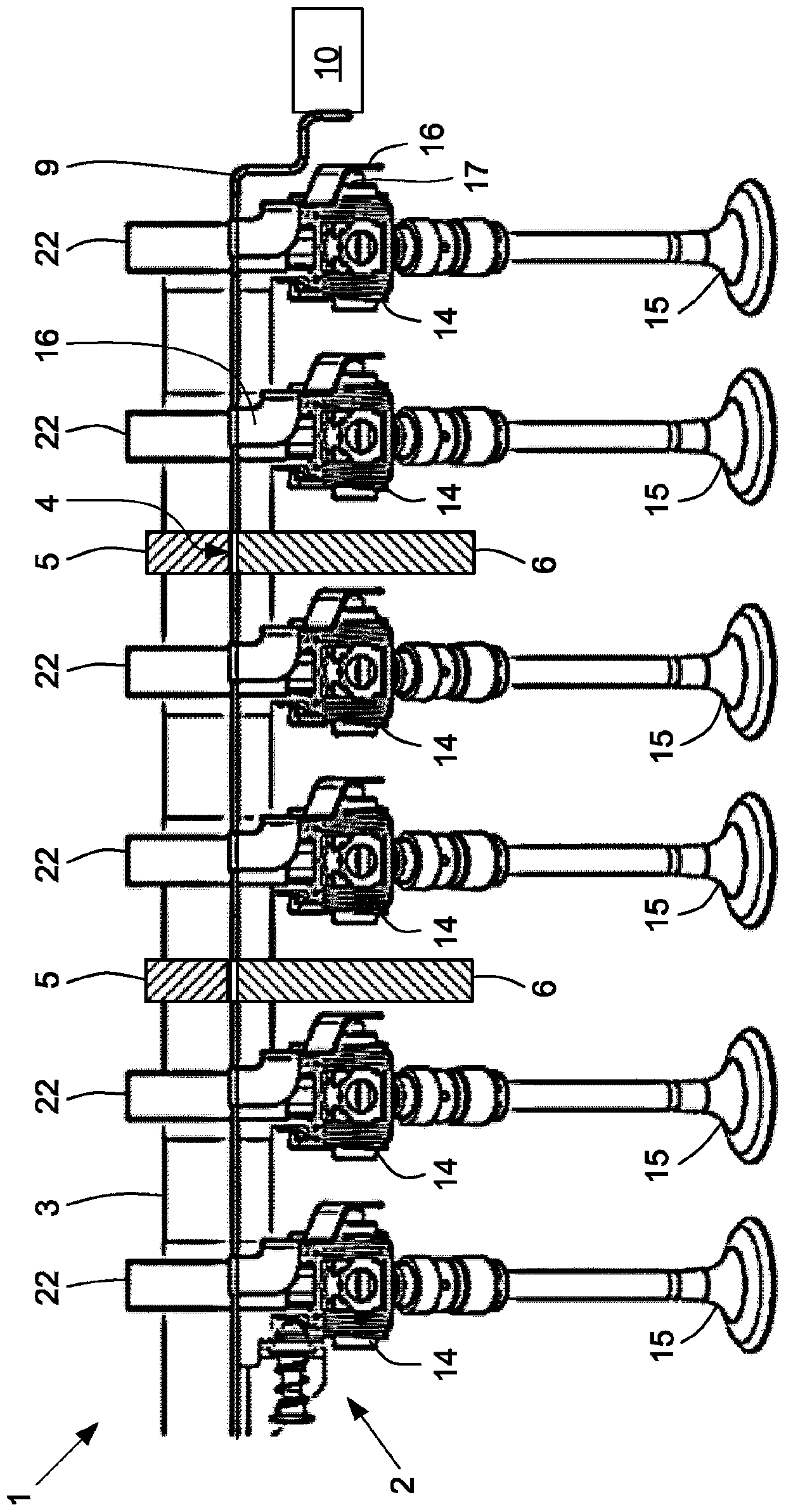
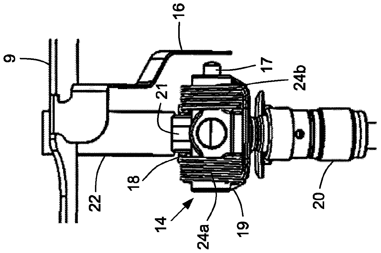
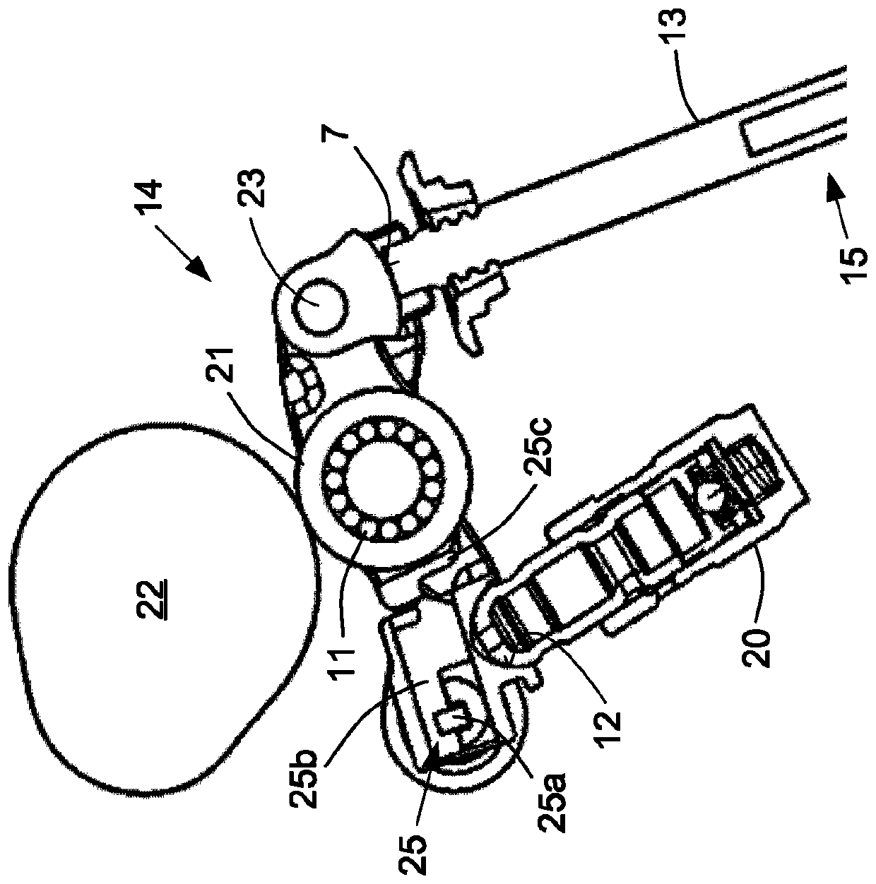
[0038] Thus, in figure 1 The cylinder head 1 of a hypothetical six-cylinder piston internal combustion engine shown in FIG. 1 has a variable valve gear 2 , each having twelve intake valves and twelve exhaust valves. The exhaust camshaft 3 is supported in the cylinder head 1 in a plurality, for example seven, of camshaft half bearing blocks 6 . In addition, several, for example seven, associated upper camshaft half-bearing caps 5 are fixedly screwed onto the parting plane 4 of the cylinder head 1 , which is also designed for accommodating a valve cover (not shown). Two camshaft half-bearing supports 6 and two camshaft half-bearing caps 5 respectively assigned to the camshaft half-bearing supports 6 are shown in an exemplary and schematically simplified manner at figure 1 shown in .

[0039] The upper camshaft half-bearing caps 5 each overlap a guide 8 arranged in the separating plane 4 as a recess in the camshaft half-bearing seat 6 , wherein the guides 8 configured as a rece...


PUM


Abstract

The present invention relates to a variable valve transmission of a piston-type internal combustion engine, which has a gas exchange valve with the same function for each cylinder. The valve stroke ispreset by a cam of a camshaft and can be transmitted to the gas exchange valve by means of a switchable pressure rod. The switching of the pressure rod, which can be guided axially movably in the transverse borehole, is connected to the longitudinally extending switching device via the connecting element. The switching device is supported above the pressure rod in a guide in the cylinder head andcan be moved longitudinally against the restoring force of the spring element by means of a linear actuator. The connecting element attaches to, engages in or fastens on the switching device above, and attaches to, engages in or fastens below on the end of the corresponding switching pin. The switching device or the guide has a three-dimensionally structured surface area that extends in the direction of motion at least on the section of the lower peripheral side of the switching device or the upper peripheral side of the guide; or the switching device and the guide have such mutually complementary surface areas.

Description

technical field [0001] The invention relates to a variable valve drive of a piston internal combustion engine, which has at least one functionally identical gas exchange valve for each cylinder in the cylinder head of the piston internal combustion engine, the valve strokes of which are respectively Predetermined by at least one cam of the camshaft and can be selectively transmitted to at least one associated gas exchange valve by means of a switchable pressure rod, wherein the pressure rods are each axially movable in a transverse bore The guided switching pin is connected via an elastic or rigid connecting element to at least one longitudinally extending switching element, which is mounted above the pressure rod parallel to the camshaft in at least one guide in the cylinder head and can be moved by means of Against the restoring force of the spring element, the linear actuator is moved longitudinally from the rest position into the switching position, wherein the connecting ...

Claims


Application Information

Patent Timeline
IPC IPC(8): F01L1/12F01L1/18F01L13/00
CPCF01L1/12F01L1/18F01L13/00F01L1/185F01L13/0005F01L2013/101F01L2810/02F01L13/0036F01L2305/00F01L1/2405F01L2001/186F01L2800/05
Inventor 阿德里安·比兰弗兰克·希姆塞尔阿尔诺·贝希施泰特
Owner SCHAEFFLER TECH AG & CO KG
Learn More