Bridge anti-collision guardrail structure and construction method thereof

A technology of anti-collision guardrails and beam structures, which is applied in the direction of bridges, bridge parts, bridge construction, etc., and can solve the problems that the anti-collision guardrails and part of the planter are hard to meet the design requirements, the construction quality is difficult to control, and the construction period is long. Achieve obvious direct and indirect economic benefits, eliminate construction quality problems, and shorten the construction period

Pending Publication Date: 2020-04-28
深圳市综合交通与市政工程设计研究总院有限公司
View PDF0 Cites 0 Cited by
  • Summary
  • Abstract
  • Description
  • Claims
  • Application Information

AI Technical Summary

Problems solved by technology

[0003] The technical problem to be solved by the present invention is to provide a bridge anti-collision guardrail structure and its construction method, aiming to solve the problem that in the prior art, the anti-collision guardrails and planters are all constructed with concrete cast-in-place, and the on-site binding steel bars are difficult to meet the design requirements. Requirements, construction quality is difficult to control, construction period is long, and the cost is uneconomical

Method used


Image

  • Bridge anti-collision guardrail structure and construction method thereof
  • Bridge anti-collision guardrail structure and construction method thereof
  • Bridge anti-collision guardrail structure and construction method thereof

Examples


Embodiment Construction

[0033] In order to make the object, technical solution and advantages of the present invention clearer, the present invention will be further described in detail below in conjunction with the accompanying drawings and embodiments. It should be understood that the specific embodiments described here are only used to explain the present invention, not to limit the present invention.

[0034] In the description of the present invention, it should be noted that the terms "center", "upper", "lower", "left", "right", "vertical", "horizontal", "inner", "outer" etc. The indicated orientation or positional relationship is based on the orientation or positional relationship shown in the drawings, and is only for the convenience of describing the present invention and simplifying the description, rather than indicating or implying that the referred device or element must have a specific orientation, or in a specific orientation. construction and operation, and therefore cannot be constru...


PUM


Abstract

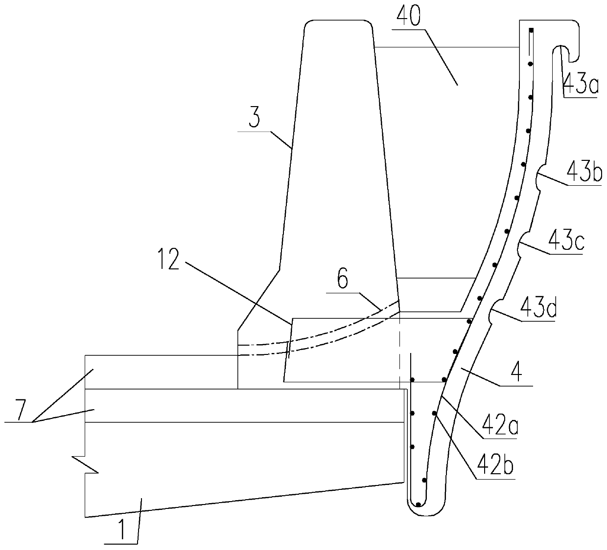
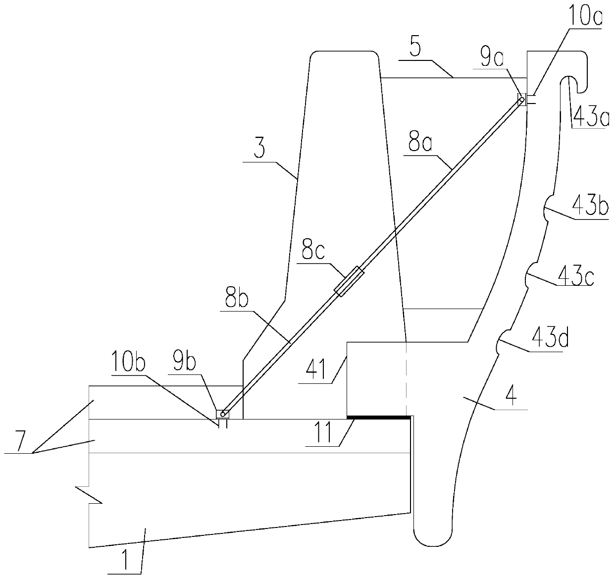
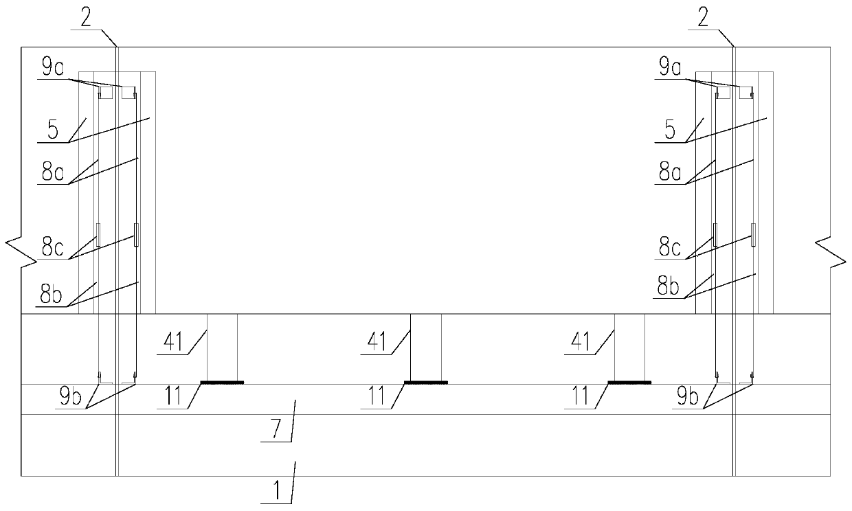
The invention is suitable for the technical field of bridge engineering, and provides a bridge anti-collision guardrail structure and a construction method thereof. The anti-collision guardrail structure comprises an anti-collision guardrail body, a prefabricated planter body, a plurality of inclined steel bars and a plurality of stiffening plates. The inner side face of the prefabricated planterbody and the outer side face of the anti-collision guardrail body are spaced by a certain distance to form a planter used for containing planting soil and plants. The prefabricated planter body is manufactured in advance before being installed, and the prefabricated planter body and the cast-in-place anti-collision guardrail body are fixedly installed on a construction site. The decorative requirements of different forms can be met in a mode of prefabricating the planter component. Meanwhile, the construction method can solve the construction quality problem caused by steel bar binding and cast-in-place concrete on site, improve the landscape quality and shorten the construction period, and achieves obvious direct and indirect economic benefits.

Description

technical field [0001] The invention belongs to the technical field of bridge engineering, and in particular relates to a bridge anti-collision guardrail structure and a construction method thereof. Background technique [0002] As the requirements of urban landscape become higher and higher, ordinary bridge anti-collision barriers are difficult to meet the needs of urban landscape. In order to increase the aesthetics of bridge anti-collision barriers, the structure of adding planters to the outside of bridge anti-collision barriers is usually used. For the anti-collision guardrails and planters, the cast-in-place concrete construction technology is adopted. When using conventional construction methods, it is necessary to bind a large number of steel bars on the bridge structure according to the planters, and then cast in-situ concrete. However, because planters generally use special-shaped and special structures, it is difficult to bind steel bars on site to meet the design...

Claims


Application Information

Patent Timeline
Patent Type & Authority Applications(China)
IPC IPC(8): E01D19/10E01D19/12E01D19/08A01G9/02E01D21/00
CPCA01G9/02E01D19/086E01D19/103E01D19/125E01D21/00
Inventor 喻寄彭群洁刘晓华韦彬唐皓曹诗定
Owner 深圳市综合交通与市政工程设计研究总院有限公司
Why Eureka
Try Eureka