Balance car
A balance car and linkage shaft technology, applied in the field of balance cars, can solve problems such as vertical pressure contrast, tilting and crashing, and achieve the effect of avoiding crash accidents and reducing the impact of bumps
- Summary
- Abstract
- Description
- Claims
- Application Information
AI Technical Summary
Problems solved by technology
Method used
Image

Examples
Embodiment 1
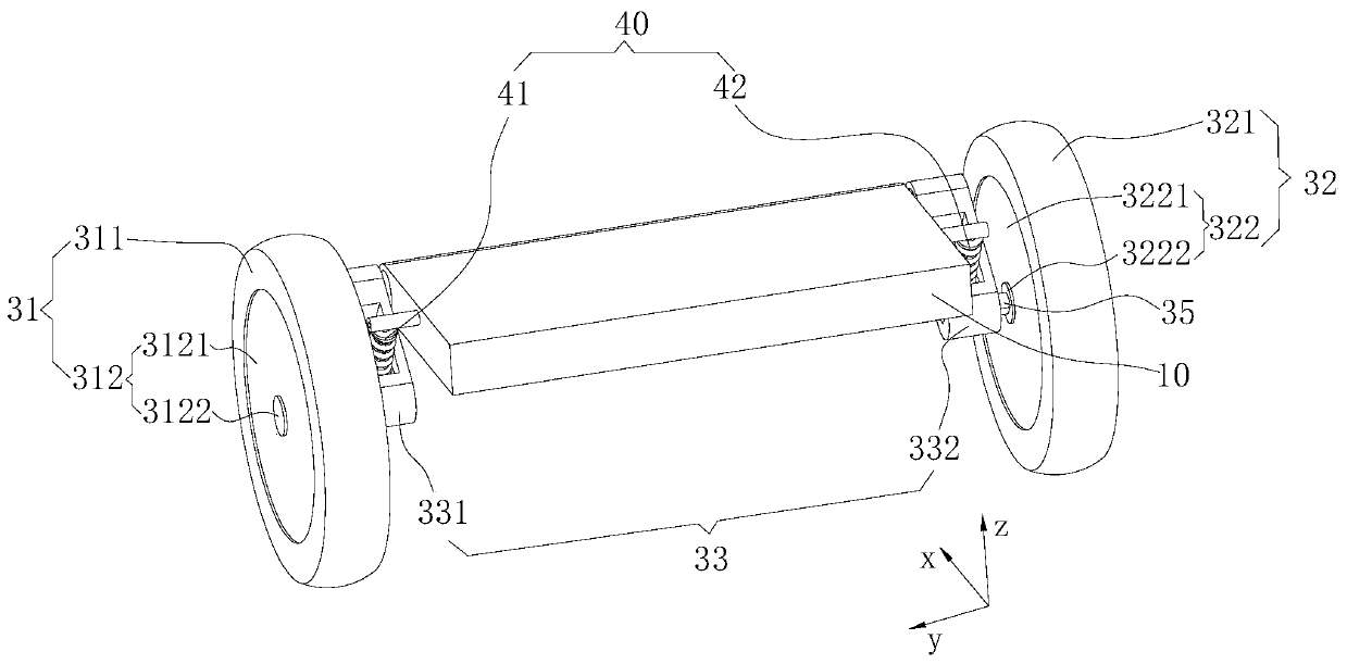
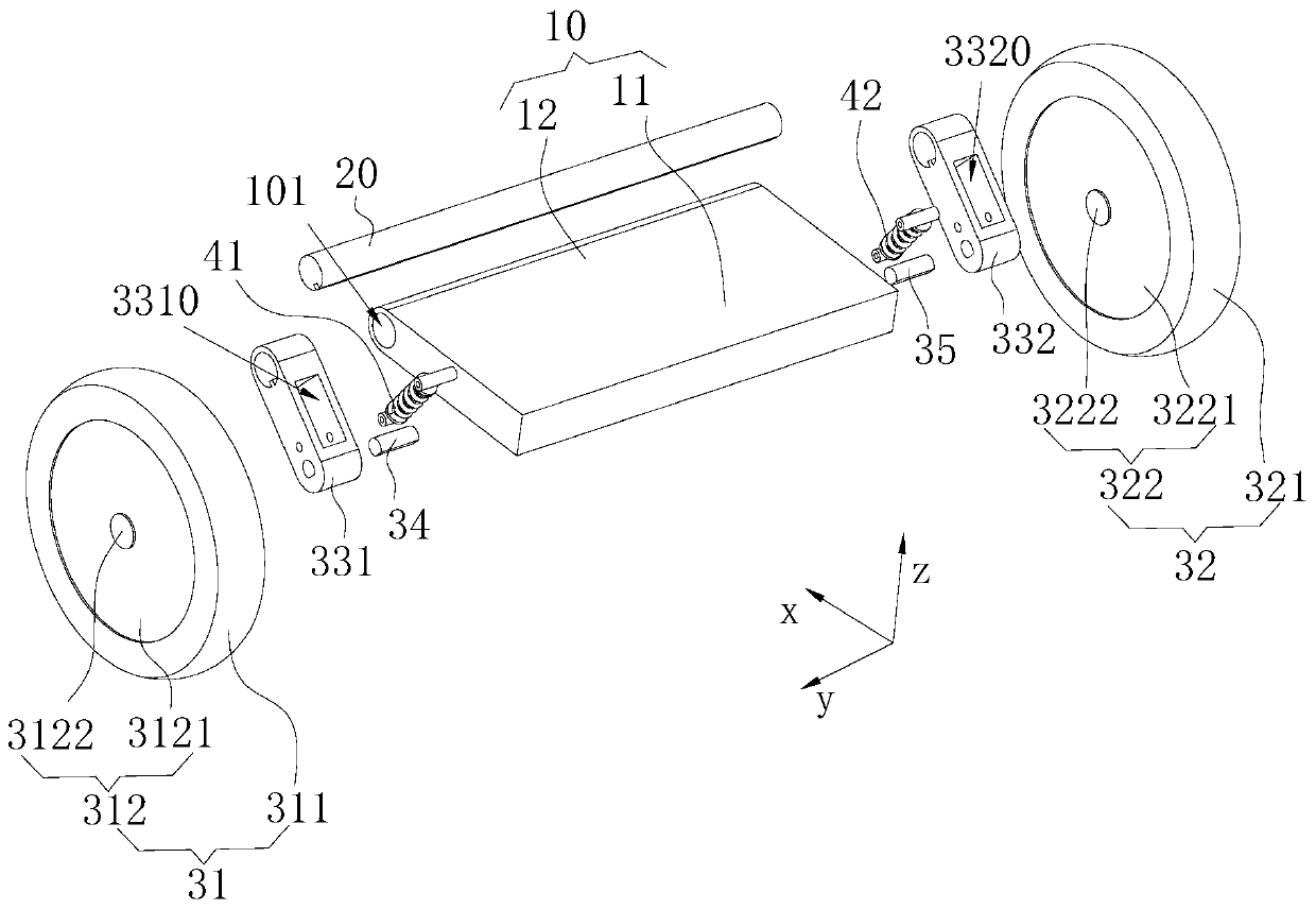
[0039] Please refer to figure 1 and figure 2 , The present invention provides a self-balancing vehicle, including a vehicle body 10 , a linkage shaft 20 , a running mechanism and a shock absorbing mechanism 40 .
[0040] Wherein, the vehicle body 10 includes a pedal 11 for the user to step on and a mounting base 12 connected to the pedal 11, the mounting base 12 is rotationally connected with the linkage shaft 20, and optionally, the linkage shaft 20 has a shaft extending in the left and right direction hole, the mounting seat 12 includes a left mounting ear 121 sleeved on the left end of the shaft hole and capable of rotating in the shaft hole, and a right mounting ear 122 sleeved on the right end of the shaft hole and capable of rotating in the shaft hole. Preferably, the mounting seat 12 A sleeve hole 101 extending in the left and right direction is opened, and the linkage shaft 20 extends in the left and right direction and passes through the sleeve hole 101 and can rota...
Embodiment 2
[0050] The structure and function of the second embodiment are similar to those of the first embodiment, and will not be repeated here. The difference lies in:
[0051] Please refer to image 3 The left wheel assembly 31 in the second embodiment of the present invention includes a left driving wheel 311 and a left motor 312. The left motor 312 has a left stator part 3122 and a left rotor part 3121 that can rotate relative to the left stator part 3122. The left wheel shaft 34 is fixedly connected to the The left stator part 3122, the left driving wheel 311 is fixedly connected to the left rotor part 3121; The sub part 3221 , the right axle 35 is fixedly connected to the right stator part 3222 , and the right driving wheel 321 is fixedly connected to the right rotor part 3221 . It can be understood that the left wheel shaft 34 does not rotate during the rotation of the left driving wheel 311, and the right wheel shaft 35 does not rotate during the rotation of the right driving ...
Embodiment 3
[0058] The mechanism and function of the third embodiment are similar to those of the second embodiment, and will not be repeated here. The difference lies in:
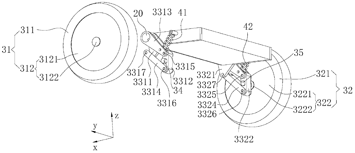
[0059] Please refer to Figure 4 Further, the left wheel shaft 34 is provided with a left cooling hole 340 in the axial direction, and the left connecting seat 3312 includes a first left seat body connected to the hole wall of the left cooling hole 340 and a hole wall connected to the left cooling hole 340 and connected to the second hole wall. A second left seat body arranged at intervals, the left main link 3313 and the first left seat body are rotationally connected through the first left rotation shaft 3315, and the left auxiliary link 3314 and the second left seat body are connected through the second left rotation shaft 3316 Rotational connection; the axial direction of the right wheel shaft 35 is provided with a right cooling hole 350, and the right connecting seat 3322 includes a first right seat body 3328 con...
PUM
 Abstract
Description
Claims
Application Information
 - Generate Ideas
- Intellectual Property
- Life Sciences
- Materials
- Tech Scout
- Unparalleled Data Quality
- Higher Quality Content
- 60% Fewer Hallucinations
Browse by: Latest US Patents, China's latest patents, Technical Efficacy Thesaurus, Application Domain, Technology Topic, Popular Technical Reports.
© 2025 PatSnap. All rights reserved.Legal|Privacy policy|Modern Slavery Act Transparency Statement|Sitemap|About US| Contact US: help@patsnap.com