Rattan braided fabric assembling structure and method
A technology of assembly structure and assembly method, which is applied to wood processing equipment, manufacturing tools, etc., can solve the problems of high labor costs, difficulty in installing rattan pieces with beveled edges, etc., and achieve the effects of beautiful appearance, improved automation, and simple process
- Summary
- Abstract
- Description
- Claims
- Application Information
AI Technical Summary
Problems solved by technology
Method used
Image
Examples
Embodiment 1
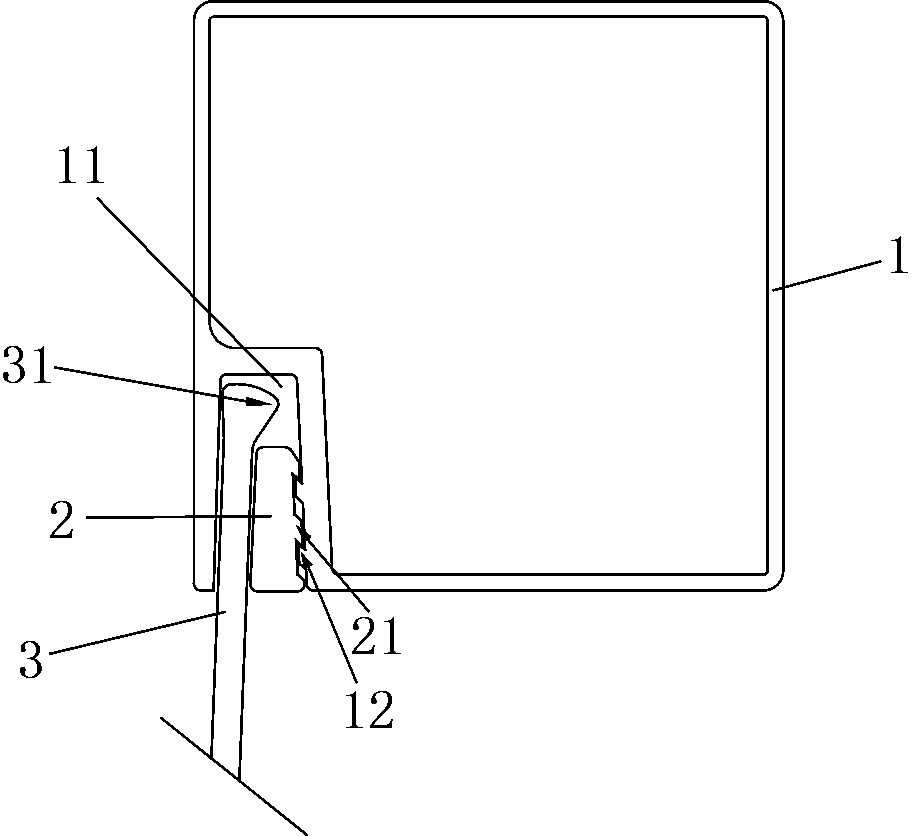
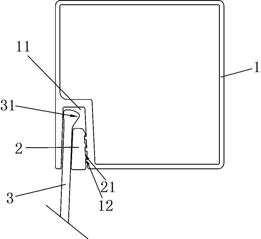
[0030] see figure 1 and figure 2 , the rattan braid assembly structure, including a frame 1, a limit piece 2 and a rattan braid 3.
[0031] The frame 1 is preferably formed by welding, and the frame 1 has an installation groove 11, the installation groove 11 is used to install the limiter 2 and the rattan braid 3, and the wall of the installation groove 11 has a snap-in position 12, and the limiter The part 2 has a snap-fit part 21 snap-fitted with the snap-fit position 12, and preferably, the limiting part 2 is a pressing bar.
[0032] The clamping position 12 is a clamping protrusion arranged on the wall of the installation groove 11 , and the clamping portion 21 is a clamping protrusion disposed on the side wall of the limiting member 2 .
[0033] There are at least two ways of cooperation between the snap-in protrusion and the snap-in protrusion. Here are only two examples of cooperation: first, the two snap-in protrusions have a circular or polygonal structure, and...
Embodiment 2
[0042] Embodiment 2: Compared with Embodiment 1, the difference lies in the structure of the locking position and the locking part, and the rest are the same.
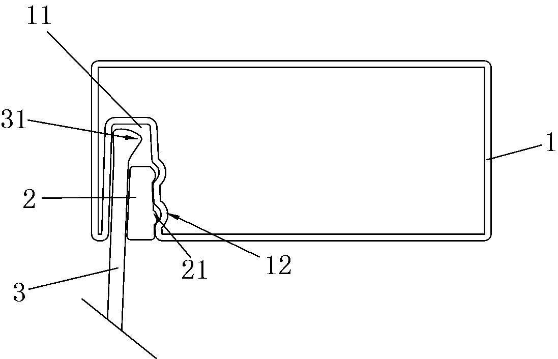
[0043] see image 3 , the clamping position 12 is a groove opened on the wall of the installation groove 11, and the clamping part 21 is a protrusion provided on the side wall of the limiting member 2 to clamp and fit with the groove. rise.
[0044] The whole composed of the rattan braid 3 and the stopper 2 is adapted to the installation groove 11, the space in the installation groove 11 is filled or nearly filled by the whole, and after the stopper 2 is pressed into the installation groove 11, the convex The lifting and the groove are engaged with each other, so that the limiting member 2 is difficult to be directly extracted from the installation groove 11, and at the same time, the rattan braid 3 is pressed by the limiting member 2, thereby stably limiting the rattan braiding 3.
Embodiment 3
[0045] Embodiment 3: Compared with Embodiment 1, the difference lies in the structure of the clamping position and the clamping part, and the rest are the same.
[0046] see Figure 4 The clamping position 12 is a protrusion provided on the wall of the installation groove 11, and the clamping part 21 is a recess provided on the side wall of the limiting member 2 to engage with the protrusion. groove.
[0047] The whole composed of the rattan braid 3 and the stopper 2 is adapted to the installation groove 11, the space in the installation groove 11 is filled or nearly filled by the whole, and after the stopper 2 is pressed into the installation groove 11, the convex The lifting and the groove are engaged with each other, so that the limiting member 2 is difficult to be directly extracted from the installation groove 11, and at the same time, the rattan braid 3 is pressed by the limiting member 2, thereby stably limiting the rattan braiding 3.
[0048] Preferably, when the lim...
PUM
 Abstract
Description
Claims
Application Information
 - R&D
- Intellectual Property
- Life Sciences
- Materials
- Tech Scout
- Unparalleled Data Quality
- Higher Quality Content
- 60% Fewer Hallucinations
Browse by: Latest US Patents, China's latest patents, Technical Efficacy Thesaurus, Application Domain, Technology Topic, Popular Technical Reports.
© 2025 PatSnap. All rights reserved.Legal|Privacy policy|Modern Slavery Act Transparency Statement|Sitemap|About US| Contact US: help@patsnap.com


