A stamping, bending and punching die

A bending and die technology used in the stamping field

Active Publication Date: 2021-05-21
苏州市本阳精密五金科技有限公司
View PDF8 Cites 0 Cited by
  • Summary
  • Abstract
  • Description
  • Claims
  • Application Information

AI Technical Summary

Problems solved by technology

[0005] There is an existing connecting piece with a U-shaped cross-section, and through holes are respectively provided on the side wall and bottom of the connecting piece. At present, there is no special mold for bending and punching the connecting piece.

Method used


Image

  • A stamping, bending and punching die
  • A stamping, bending and punching die
  • A stamping, bending and punching die

Examples


Embodiment Construction

[0025] The present invention will be further described in detail below in conjunction with the accompanying drawings and embodiments.

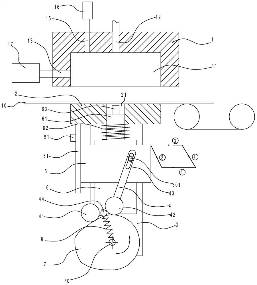
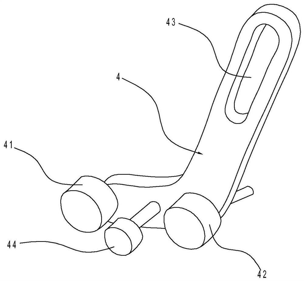
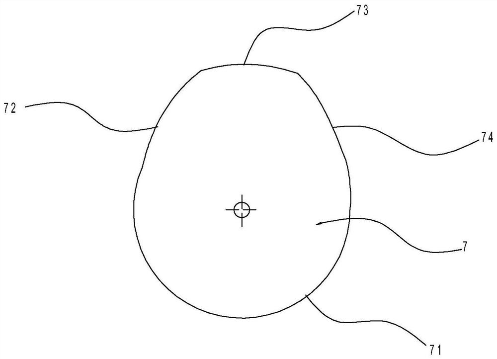
[0026] Such as Figures 1 to 8 As shown, the stamping, bending and punching die in this implementation includes an upper die 1, a lower die 2, a driving cam 7, a fixed plate 3, a horizontal slide plate 5, a vertical slide plate 6, a bending rod 4, a first roller 41, a Two rollers 42, hold down spring 8, support rod 51, left punch 91, stamping spring 62, upper punch 63, suction pump 17 and blowing pump 16.

[0027]Wherein, the upper die 1 is fixedly arranged, and the lower die 2 is set in motion, and the upper die 1 is formed with a cavity 11 with a downward opening for carrying out U-shaped bending to the plate 10, and on the bottom of the cavity 11 An upper punching hole 12 is provided, a left punching hole 13 is provided on the left side wall of the cavity 11, a right punching hole 14 is provided on the right side wall of the cavity 11, and...


PUM


Abstract

The invention discloses a stamping, bending and punching die, which is characterized in that it comprises a fixed upper die and a moving lower die, a fixed plate is arranged under the upper die, and a vertical sliding plate is arranged to slide vertically on the fixed plate. The lower part of the vertical slide is provided with a driving cam, the upper part of the vertical slide is horizontally slid and provided with a horizontal slide, the left end of the horizontal slide is vertically provided with a left punch, the top of the vertical slide is vertically provided with an upper punch, and the lower die is provided with a through hole. , the support column is provided with a stamping spring, the upper end of the stamping spring is connected to the lower die, the lower part of the vertical slide is provided with a bent bar, the upper end of the bent bar is provided with a bar-shaped hole, and the horizontal slide is provided with a limiter for passing through the bar-shaped hole. As for the positioning post, the lower end of the curved rod is provided with a first roller and a second roller which are in contact with the driving cam, and a compression spring is arranged between the driving cam and the curved rod. The invention provides a stamping, bending and punching die, which realizes one-time bending and punching operations on U-shaped connectors.

Description

technical field [0001] The invention relates to the stamping field, in particular to a stamping, bending and punching die. Background technique [0002] In cold stamping, the stamping die processes the material (metal or non-metal) into parts or semi-finished products. During stamping, the mold installed on the press is used to apply pressure to the material to cause separation or plastic deformation to obtain the required parts. Usually a pair of stamping dies can realize one-time surface forming, cutting, stretching, bending, punching and other operations on the material. [0003] For example, the Chinese utility model patent with the existing publication number CN 207971236 U discloses "A Bending Die for Plates", which includes a workbench and a hydraulic cylinder. The bottom of the workbench is provided with supporting legs, and the right end of the workbench A support plate is hinged, and the support plate and the workbench are set at an obtuse angle. An oil cylinder A...

Claims


Application Information

Patent Timeline
Patent Type & Authority Patents(China)
IPC IPC(8): B21D35/00B21D5/02B21D28/24
CPCB21D5/02B21D28/24B21D35/001B21D35/002
Inventor 郑六军
Owner 苏州市本阳精密五金科技有限公司
Why Eureka
Try Eureka