stent graft
A stent-graft, covering technology, applied in the field of medical devices, can solve problems such as no solution found
- Summary
- Abstract
- Description
- Claims
- Application Information
AI Technical Summary
Problems solved by technology
Method used
Image
Examples
Embodiment 1
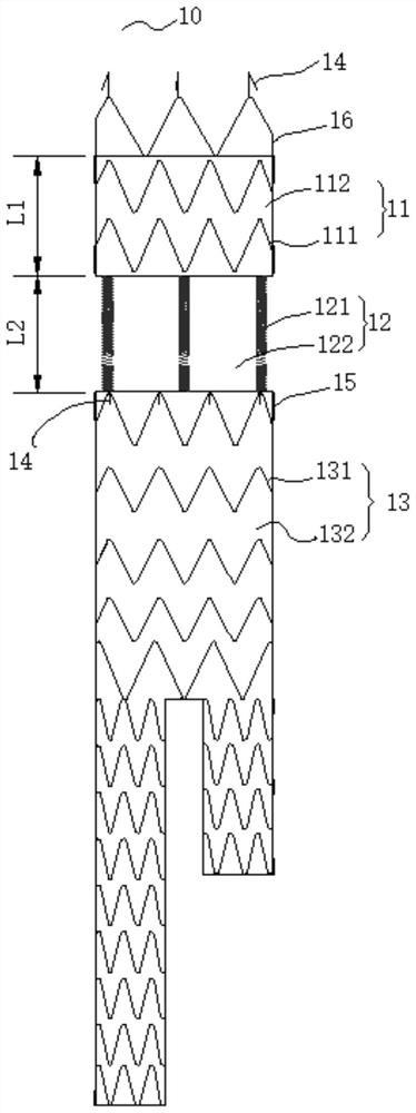
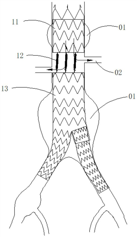
[0026] like figure 1 As shown, the stent-graft 10 of this embodiment includes a first covering section 11 , a second covering section 13 , and a connecting section 12 connecting the first covering section 11 and the second covering section 13 . Specifically, the connecting segment 12 connects the distal end of the first covering segment 11 and the proximal end of the second covering segment 13 .
[0027] The first film section 11 includes a first support member 111 and a first film 112. The first film 112 covers the inner surface or the outer surface of the first support member 111 so that the first film section 11 has a circumferentially closed hollow. lumen. The number of the first support members 111 may be multiple. In this case, the multiple first support members 111 are axially connected by the first coating film 112 . Similarly, the second film section 13 includes a plurality of second support members 131 and a second film 132 , and the plurality of second support mem...
Embodiment 2
[0039] The stent-graft of this embodiment is substantially the same in structure as the stent-graft of Embodiment 1, and the difference lies in the structure of the connecting section. like Figure 4 As shown, the connecting section 22 of the stent-graft in this embodiment includes a plurality of bare stents 223 , and the plurality of bare stents 223 are axially arranged and connected by elastic members 221 . Every two adjacent bare brackets 223 are connected by at least one elastic member 221 . The bare stent can be made of braided wire, and two ends of the braided wire can be fixedly connected by a fixing member 224 (eg, a sleeve), thereby forming a circumferentially closed annular bare stent. The end of the elastic piece 221 can also be fixed on the bare bracket by the fixing piece 224 . The elastic members 221 connecting the plurality of bare stents 223 can be approximately in a straight line in the axial direction and extend along the length direction of the stent-graft...
Embodiment 3
[0043] The stent-graft of this embodiment is substantially the same in structure as the stent-graft of Embodiment 1, and the difference lies in the structure of the connecting section. like Figure 5 As shown, the connecting section 32 of the stent-graft in this embodiment includes at least two wave rings arranged in the axial direction, wherein the proximal end of one wave ring is connected with the distal end portion of the other wave ring. Specifically, the wave ring is a W-shaped wave ring, including a plurality of wave crests 324 and a plurality of wave troughs 325 . The number of wave crests or wave troughs of the multiple wave circles may be the same or different, and preferably, the wave crest of one wave circle has the same number of wave troughs as the adjacent wave circles located at the proximal end thereof.
[0044] For the purpose of description, three adjacent wave circles are defined as a first wave circle 321 , a second wave circle 322 and a third wave circle...
PUM
 Abstract
Description
Claims
Application Information
 - R&D Engineer
- R&D Manager
- IP Professional
- Industry Leading Data Capabilities
- Powerful AI technology
- Patent DNA Extraction
Browse by: Latest US Patents, China's latest patents, Technical Efficacy Thesaurus, Application Domain, Technology Topic, Popular Technical Reports.
© 2024 PatSnap. All rights reserved.Legal|Privacy policy|Modern Slavery Act Transparency Statement|Sitemap|About US| Contact US: help@patsnap.com


