
Calibration jig, calibration device and calibration method for proximity switch

A technology of proximity switch and calibration device, applied in electric switches, magnetic field micro-mechanical switches, magnetic field/electric field switches, etc., can solve the problem of inconvenient manual operation of terminal equipment calibration, and achieve the effect of simple structure and convenient operation

Active Publication Date: 2020-04-24
成都欧珀移动通信有限公司
View PDF4 Cites 1 Cited by
  • Summary
  • Abstract
  • Description
  • Claims
  • Application Information

AI Technical Summary

Problems solved by technology

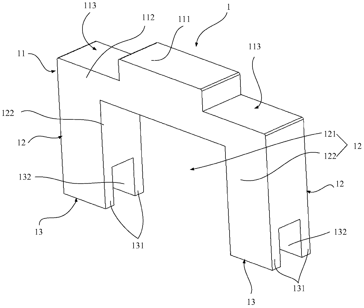
[0004] In view of this, the embodiment of the present application expects to provide a calibration fixture, a calibration device, and a calibration method of a proximity switch to solve the problem of inconvenient manual operation of terminal equipment calibration

Method used


Image

  • Calibration jig, calibration device and calibration method for proximity switch
  • Calibration jig, calibration device and calibration method for proximity switch
  • Calibration jig, calibration device and calibration method for proximity switch

Examples


Embodiment Construction

[0032] It should be noted that, in the case of no conflict, the embodiments in the application and the technical features in the embodiments can be combined with each other. Undue Limitation of This Application.

[0033] The orientation terms described in this application are only for the convenience of describing the application and simplifying the description, rather than indicating or implying that the device or element referred to must have a specific orientation, be constructed and operated in a specific orientation, and therefore cannot be construed as a reference to this application. limits.

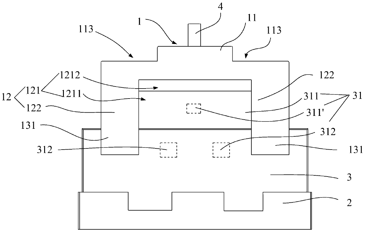
[0034] Before describing the embodiment of the present application, the calibration principle of the proximity switch will be introduced. see image 3 When calibrating the proximity switch 31 of the terminal device 3, the key 311 of the toggle proximity switch 31 is moved to a different position, and the inductive element 312 in the proximity switch 31 records the position of th...


PUM


Abstract

The embodiment of the invention provides a calibration jig, a calibration device and a calibration method for a proximity switch. The calibration jig comprises a shifting part and a clamping part. Theshifting part is used for applying force to shift a key of the proximity switch to move, the clamping part is provided with an accommodating cavity for accommodating the key, and the clamping part isconnected with the shifting part and used for clamping the key. According to the calibration jig provided by the embodiment of the invention, the clamping part is connected with the key, and the keycan be driven to move by operating the shifting part, so that the calibration operation of the proximity switch is more convenient and faster.

Description

technical field [0001] The present application relates to the technical field of terminal equipment, in particular to a calibration fixture, calibration device and calibration method for a proximity switch. Background technique [0002] By calibrating the proximity switch of the terminal equipment such as the Hall switch, the position information of the keys of the proximity switch in different states is obtained and recorded. When in use, the position information of the key obtained through calibration is used as a basis for judging whether the terminal device switches states. [0003] At present, in the process of calibration, the method of manually toggling the buttons is adopted, but most of the buttons are relatively small, and manual operation is very inconvenient. Contents of the invention [0004] In view of this, the embodiment of the present application expects to provide a calibration fixture, a calibration device, and a calibration method for a proximity switc...

Claims


Application Information

Patent Timeline
Patent Type & Authority Applications(China)
IPC IPC(8): H01H36/00
CPCH01H36/00H01H2036/0093
Inventor 李钰成
Owner 成都欧珀移动通信有限公司
Learn More