
Electric energy meter intelligent base with load identification function and implementation method

A technology of electric energy meters and loads, which is applied in the direction of measuring electric variables, measuring devices, instruments, etc., can solve the problems of waste of electric power materials, and the service life of electric energy meters has not expired, and achieve the effect of uniform appearance and compact hardware structure

Inactive Publication Date: 2020-04-24
JIANGSU INTELEVER ENERGY TECH CO LTD
View PDF5 Cites 3 Cited by
  • Summary
  • Abstract
  • Description
  • Claims
  • Application Information

AI Technical Summary

Problems solved by technology

[0004] This kind of electric energy meter with load identification function is very suitable for new users and can be installed and used directly; but for the vast stock market, the number of electric meters has reached hundreds of millions, and in order to meet the advanced needs of users for power consumption, it must be dismantled The original electric energy meter, the installation of electric energy meter with load identification will bring huge capital investment; at the same time, some electric energy meters have not yet reached the service life, which will cause a great waste of power materials

Method used


Image

  • Electric energy meter intelligent base with load identification function and implementation method
  • Electric energy meter intelligent base with load identification function and implementation method
  • Electric energy meter intelligent base with load identification function and implementation method

Examples


Embodiment Construction

[0026] Below in conjunction with accompanying drawing and specific embodiment, further illustrate the present invention, should be understood that these embodiments are only for illustrating the present invention and are not intended to limit the scope of the present invention, after having read the present invention, those skilled in the art will understand various aspects of the present invention Modifications in equivalent forms all fall within the scope defined by the appended claims of this application.

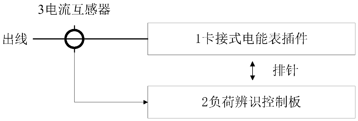
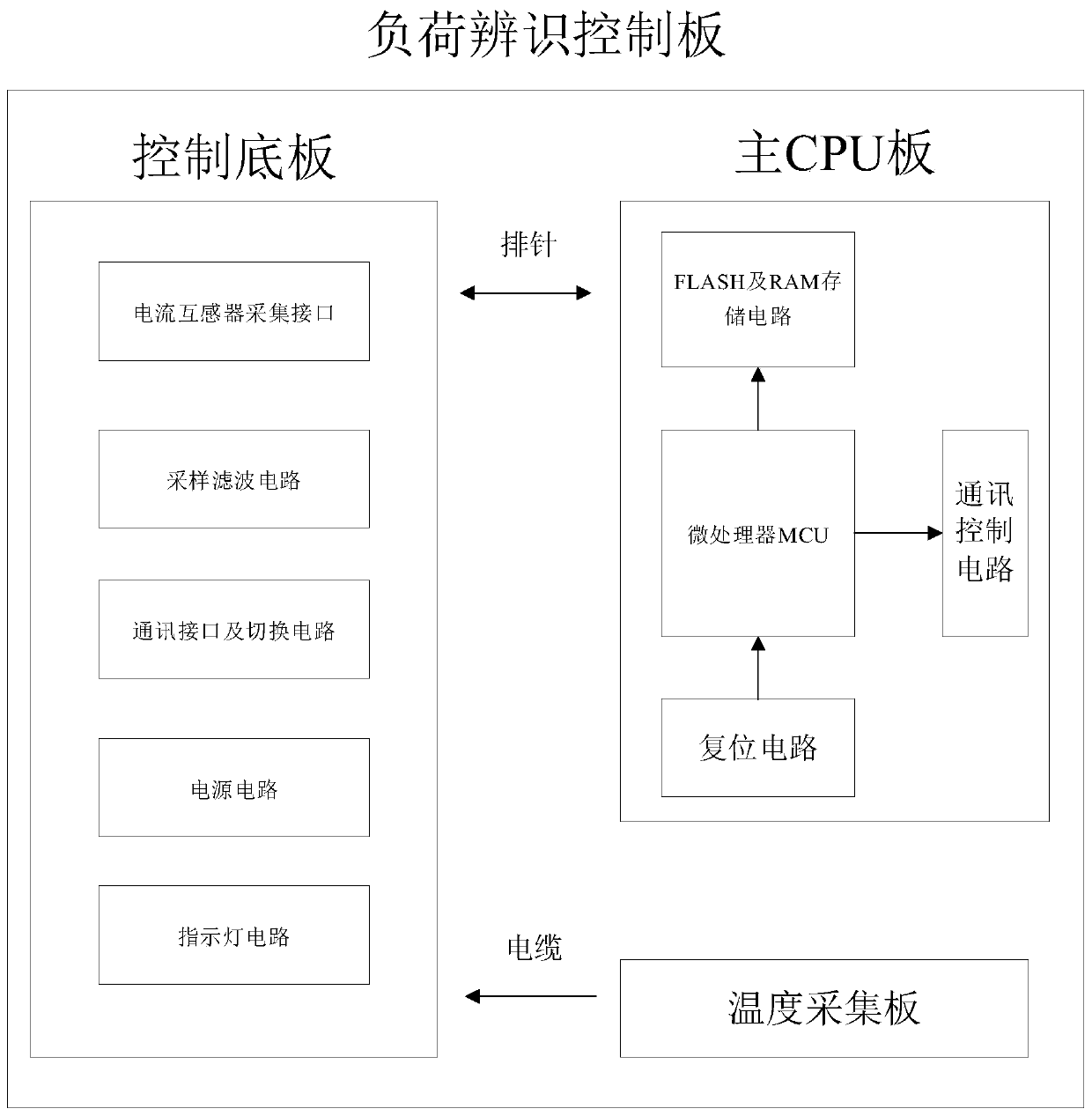
[0027] Such as figure 1 shown, see figure 1 As shown, the hardware structure of the electric energy meter intelligent base with load identification function includes snap-on electric energy meter connectors, an identification function control board, and a current transformer.

[0028] The overall structure of the smart base of the electric energy meter adopts a two-layer, stacking design. The whole intelligent base seen from the outside is the electric energy meter con...


PUM


Abstract

The invention discloses an electric energy meter intelligent base with a load identification function. The electric energy meter intelligent base comprises a clamping type electric energy meter connector arranged at an outgoing line of an electric energy meter, a load identification control panel and a current transformer. The clamping type electric energy meter connector is connected with the load identification control panel, and the current transformer is connected with the load identification control panel. The clamping type electric energy meter connector is used for being connected withthe electric energy meter, and the load identification control panel collects the current and voltage of the outgoing line of the electric energy meter, the temperature of the electric energy meter connector and the information of an electric energy meter setting switch. The hardware structure is compact, the appearance is unified, and the base can be realized on the basis of an original electricenergy meter connector without either replacing the original electric energy meter or changing the wiring of the original electric energy meter. A resident user load identification function can be realized by collecting user current and voltage data and analyzing, calculating and processing the data through a specific algorithm, and power utilization advanced measurement functions such as follow-up power utilization monitoring and diagnosis, power failure active reporting and the like can be realized in an extended manner.

Description

technical field [0001] The invention relates to a load identification method for a smart base of an electric energy meter with a load identification function, and belongs to the technical fields of smart grid and smart electricity utilization. Background technique [0002] With the improvement of people's living standards in our country, the demand of residential users for lean energy utilization services is also growing. At present, the power grid company can only push the total household electricity consumption information to the users every day, and it is difficult to monitor the electricity consumption of the main electrical appliances of the users, and cannot provide residents with refined energy consumption services such as further household energy efficiency evaluation and home appliance working condition acquisition. [0003] In order to solve the above problems, the research and practical application of advanced measurement such as non-intrusive load identification ...

Claims


Application Information

Patent Timeline
IPC IPC(8): G01R22/06G01R22/10
CPCG01R22/065G01R22/10
Inventor 王永生耿树军李振杰何朝伟
Owner JIANGSU INTELEVER ENERGY TECH CO LTD
Learn More