A compact air compressor

An air compressor, compact technology, used in mechanical equipment, machines/engines, liquid variable capacity machinery, etc., can solve the problems of unstable commutation, difficult maintenance, instability, etc., to increase the service life and the degree of automation The effect of high and low processing cost

Active Publication Date: 2021-07-30
常州市健力电气有限公司
View PDF0 Cites 0 Cited by
  • Summary
  • Abstract
  • Description
  • Claims
  • Application Information

AI Technical Summary

Problems solved by technology

[0002] With the large-scale application of large-scale mechanical equipment, the use of hydraulic drive technology in the field of air compressor application technology is becoming more and more mature. The traditional air compressor uses a crank connecting rod mechanism to realize the reciprocating movement of the piston in the cylinder and then compress the air. The output pulse of the air compressor of this method is large, unstable, and it is easy to get stuck under severe working conditions. In addition, most of the reversing valves that realize the reciprocating motion of the piston in the current hydraulic air compressors use electromagnetic reversing valves and displacement sensors. Cooperate with the control of the reversing, the sensor is controlled by the proximity switch, the reversing is unstable and unreliable; the control circuit part of the reversing device is controlled by the circuit board, because the circuit board is a non-standard part, and it is difficult to manufacture and process, and repair after damage It is very difficult; if the existing reversing device is continuously energized for a long time, it is easy to damage small devices, which cannot meet the requirements of long-term energization, and also affects the production efficiency to a certain extent; at the same time, when the piston moves to the terminal Impact collision of the cylinder block, resulting in collision noise and collision damage

Method used


Image

  • A compact air compressor
  • A compact air compressor
  • A compact air compressor

Examples


Embodiment Construction

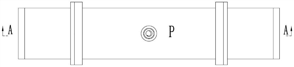
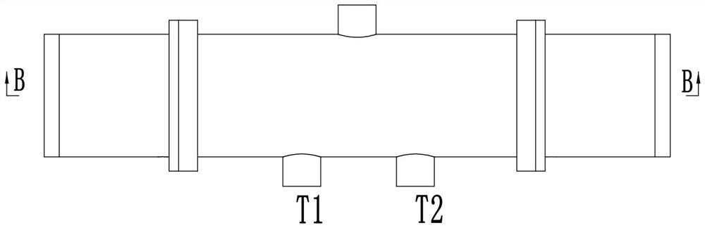
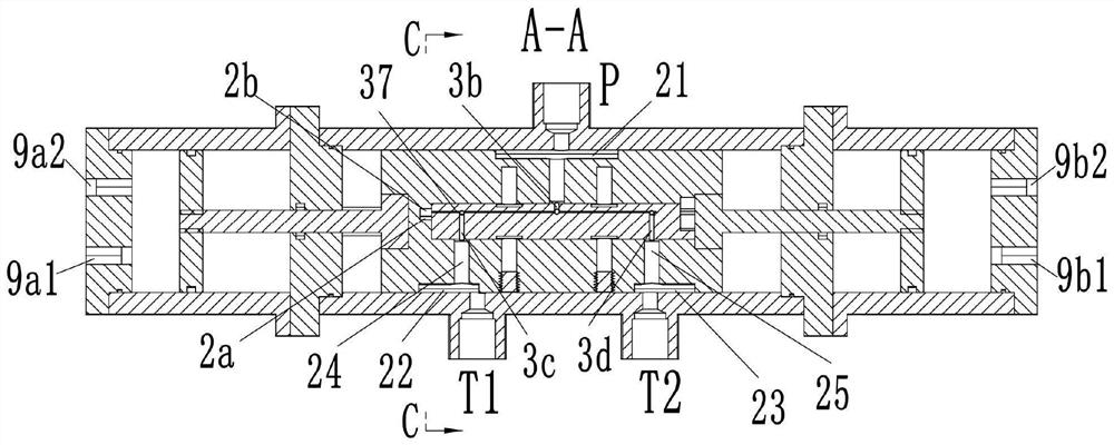
[0025] see Figure 1-25 As shown, a compact air compressor includes a body 1, the body 1 is provided with a left and right through installation hole 101, the left end of the body 1 is fixedly installed with a left end cover 5a, and the right end is fixedly installed with a right end cover 5b; The piston body 2 that moves left and right is slidably connected in the installation hole 101, and the piston body 2 is provided with two penetrating guide sliding holes 201 along its moving direction. The anti-rotation guide slide bar 9 slidingly connected in the guide slide hole 201; the left pump casing 6a is fixedly installed on the left side of the left end cover 5a, and the left cover 8a is fixedly installed on the left end of the left pump casing 6a, The right side of the right end cover 5b is fixedly equipped with a right pump casing 6b, and the right end of the right pump casing 6b is fixedly installed with a right cover 8b; The left connecting rod 4a in the pump casing 6a and ...


PUM


Abstract

The invention discloses a compact air compressor, which comprises a machine body, a left end cover is fixedly installed on the left end of the machine body, and a right end cover is fixedly installed on the right end of the machine body; The left pump casing is fixedly installed, the left end of the left pump casing is fixedly installed with a left cover, the right side of the right end cover is fixedly installed with a right pump casing, and the right end of the right pump casing is fixedly installed with a right cover; the piston body The left end is fixedly installed with a left connecting rod, and the right end is fixedly installed with a right connecting rod. The left end of the left connecting rod is provided with a left piston, and the right end of the right connecting rod is provided with a right piston; the outer surface of the body is provided with a P oil port, T1 oil port, T2 oil port; the piston body is provided with a control assembly for controlling the piston body to move left and right in the installation hole; the outer circumference of the piston body is provided with a first communication groove, a second communication groove, and a third communication groove; The press is not only simple in structure and small in size, but also can control the automatic reciprocating movement of the piston body without electronic control.

Description

technical field [0001] The invention belongs to the technical field of air compressors, and in particular relates to a compact air compressor. Background technique [0002] With the large-scale application of large-scale mechanical equipment, the use of hydraulic drive technology in the field of air compressor application technology is becoming more and more mature. The traditional air compressor uses a crank connecting rod mechanism to realize the reciprocating movement of the piston in the cylinder and then compress the air. The output pulse of the air compressor of this method is large, unstable, and it is easy to get stuck under severe working conditions. In addition, most of the reversing valves that realize the reciprocating motion of the piston in the current hydraulic air compressors use electromagnetic reversing valves and displacement sensors to match each other. Cooperate with the control of the reversing, the sensor is controlled by the proximity switch, the reve...

Claims


Application Information

Patent Timeline
Patent Type & Authority Patents(China)
IPC IPC(8): F04B39/00F04B39/10F04B39/12F04B35/02
CPCF04B9/103F04B39/0016F04B39/0027F04B39/10F04B39/121
Inventor 邵立坤
Owner 常州市健力电气有限公司
Why Eureka
Try Eureka