Rear table plate of seat
A table and seat technology, applied in the special position of the vehicle, transportation and packaging, vehicle parts, etc., can solve the problems of troublesome installation and follow-up maintenance, complex structure, etc., and achieve convenient follow-up maintenance, high comfort, and space occupation small effect
- Summary
- Abstract
- Description
- Claims
- Application Information
AI Technical Summary
Problems solved by technology
Method used
Image
Examples
Embodiment 1
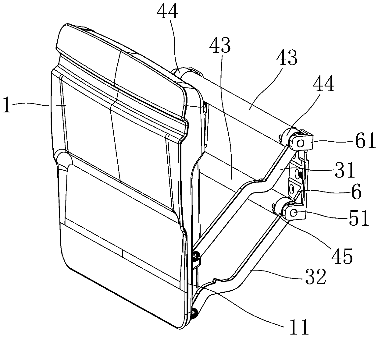
[0031] Depend on Figure 1 to Figure 6 As shown, a seat back table of the present invention includes a seat and a table 1, the seat is composed of a seat body and a seat back shell 2, and the seat back shell 2 has a table accommodating cavity 21 that penetrates front and back . Wherein, the table top 1 is composed of a table top skeleton board and a shell.
[0032]The back side of the seat body is provided with two rotating shafts arranged in the left and right directions. The two rotating shafts are respectively the first rotating shaft 41 fixed with the first connecting rod 31 and the second rotating shaft 42 fixed with the second connecting rod 32. The first connecting rod The front end of the rod 31 is fixed to the first rotating shaft 41, the rear end of the first connecting rod 31 is rotatably fixed to the table 1, the front end of the second connecting rod 32 is fixed to the second rotating shaft 42, and the rear end of the second connecting rod 32 is rotatable to the ...
Embodiment 2
[0040] Depend on Figure 8 As shown, the difference between this embodiment and Embodiment 1 is that a limit block is provided at the end of the fixed head 40 at the end of the rotating shaft. The fixed head 40 passes through the matching hole of the second fixed block 62 and is fixed to the limit block. The second fixed block 62 is limited between the limit block and the rotating shaft. The circumferential outer wall of the fixed head 40 is recessed to form an annular groove 48 , The limit block is in the shape of a spring and is located in the annular groove 48 .
Embodiment 3
[0042] Depend on Figure 9 and Figure 10 As shown, the difference between this embodiment and Embodiment 1 lies in the difference in the shape of the fixing protrusion and the fixing groove between the output shaft 51 and the output shaft installation hole 64, and the interfitting limiting structure is provided between the rotating shaft and the first fixing block 61, The fixing block and the bracket 6 are fixed by fasteners rather than integrated. The opposite sides of the outer wall of the end of the output shaft 51 are recessed to form a fixing groove and make the output shaft 51 a double-plane structure. The output shaft mounting hole 64 of the first fixing block 61 constitutes a fixing protrusion extending into the fixing groove so that the output shaft can be installed. The shape of the inner edge of the hole is the same as that of the outer edge of the output shaft 51 . Between the rotating shaft and the fixed block, there is a limit structure that cooperates with ea...
PUM
 Abstract
Description
Claims
Application Information
 - R&D Engineer
- R&D Manager
- IP Professional
- Industry Leading Data Capabilities
- Powerful AI technology
- Patent DNA Extraction
Browse by: Latest US Patents, China's latest patents, Technical Efficacy Thesaurus, Application Domain, Technology Topic, Popular Technical Reports.
© 2024 PatSnap. All rights reserved.Legal|Privacy policy|Modern Slavery Act Transparency Statement|Sitemap|About US| Contact US: help@patsnap.com


