Gear shifting mechanism for transmission

A shifting mechanism and transmission technology, applied in the direction of instruments, controlled components, mechanical equipment, etc., can solve the problems of low precision, low rotation speed, and difficult integration, so as to improve shifting accuracy, reduce shifting time, and improve The effect of shift comfort

Pending Publication Date: 2020-04-21
WANXIANG
View PDF0 Cites 2 Cited by
  • Summary
  • Abstract
  • Description
  • Claims
  • Application Information

AI Technical Summary

Problems solved by technology

[0003] Among the existing technical schemes, the first scheme adopts pneumatic and hydraulic shifting. Since the air pressure and hydraulic pressure are difficult to control when shifting gears, the shifting process cannot be precisely controlled according to the shifting strategy, and the shifting performance cannot be controlled; the second one scheme, due to the use of a deceleration mechanism, the entire shift mechanism is more complicated, the integration is difficult, and the cost is high
The hub structure is large, the precision is low, and a low rotation speed is required. The transmission efficiency of the worm gear is low and the heat generation is large.

Method used


Image

  • Gear shifting mechanism for transmission
  • Gear shifting mechanism for transmission

Examples


Embodiment

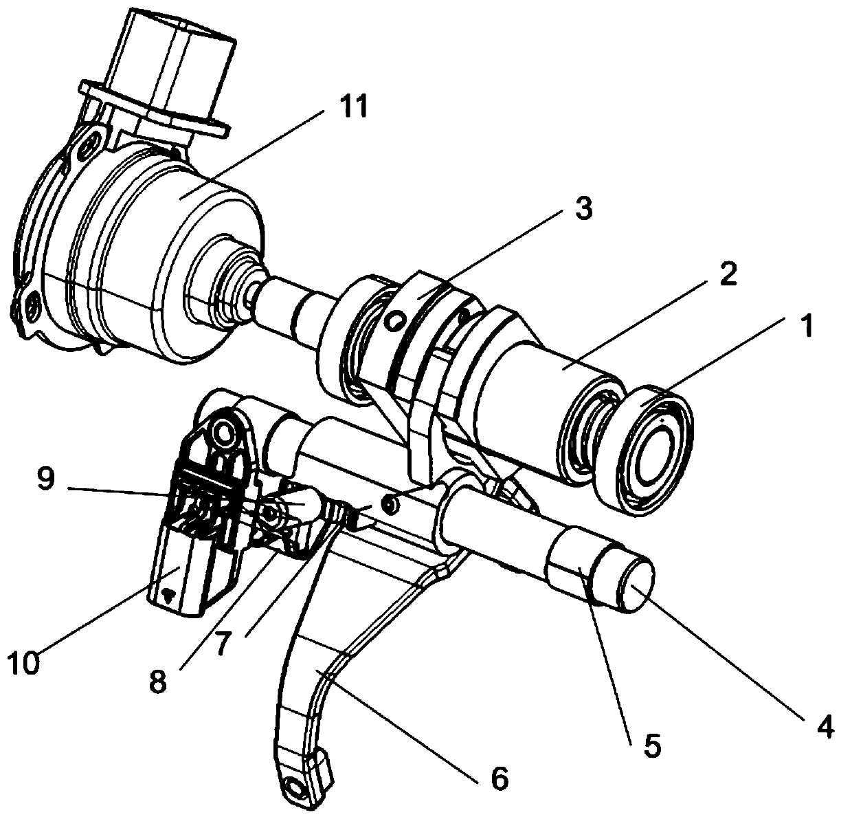
[0022] Such as figure 1 , 2 As shown, this embodiment provides a shift mechanism for a transmission, including a bearing 1, a rolling screw 2, a nut 3, a guide rod 4, a sliding sleeve 5, a shift fork 6, a limit block 7, a magnet 8, and an elastic cylinder Pin 9, sensor 10, and motor 11. In this scheme, the motor directly drives the rolling screw, and the rolling screw is fixedly connected to the guide rod through a nut, which drives the guide rod to move axially, and then drives the shift fork to move axially to realize gear shifting. When shifting, the transmission TCU controls the speed of the shifting motor according to the shifting strategy to ensure better shifting comfort when the shifting time is relatively small. In addition, there is a limited self-locking device on the shift fork. After shifting gears, the elastic cylindrical pin is located in the groove of the limit block to ensure that the synchronizer will not be out of gear when the corresponding gear is in posi...


PUM


Abstract

The invention provides a gear shifting mechanism for a transmission, the quick gear shifting of the transmission can be ensured, the gear shifting process can be accurately controlled, the comfort ofgear shifting is ensured, the structure is simple, the cost is low, and a limiting self-locking function is ensured at the same time. The gear shifting mechanism for the transmission comprises a motor, a rolling screw rod, a guide rod and a shifting fork. The motor is in driving connection with the rolling screw rod; the rolling screw rod is connected with the guide rod, the shifting fork is arranged on the guide rod, and the shifting fork can be driven to achieve gear shifting through the axial movement of the guide rod.

Description

technical field [0001] The invention relates to the field of automobile manufacturing, and in particular relates to a shift mechanism for a transmission. Background technique [0002] The existing transmission shifting technical schemes mainly include two types. The first scheme is to push the shift lever to move through the air pressure and hydraulic mechanism, thereby driving the shift fork to shift gears. The second scheme is to use a motor as the power source for shifting. The speed is relatively high, and the motor output is slowed down and the torque is increased through the gear set, and then the shift hub or worm gear is driven to push the shift fork to shift gears. [0003] Among the existing technical schemes, the first scheme adopts pneumatic and hydraulic shifting. Since the air pressure and hydraulic pressure are difficult to control when shifting gears, the shifting process cannot be precisely controlled according to the shifting strategy, and the shifting perf...

Claims


Application Information

Patent Timeline
IPC IPC(8): F16H63/30F16H63/32
CPCF16H63/32F16H63/304F16H2063/3063
Inventor 杨文权朱思涵陈江魏巍
Owner WANXIANG
Why Eureka
Try Eureka