Control valve for heating and/or cooling system

A technology for controlling valves and pressure, applied in the field of heating and/or cooling facilities, can solve problems such as leakage across the diaphragm, and achieve the effect of reducing leakage

Active Publication Date: 2020-04-17
FLOWCON INT
View PDF7 Cites 2 Cited by
  • Summary
  • Abstract
  • Description
  • Claims
  • Application Information

AI Technical Summary

Problems solved by technology

However, this solution only applies when the valve is fully closed, and leakage across the diaphragm can still occur when the valve is not fully closed

Method used


Image

  • Control valve for heating and/or cooling system
  • Control valve for heating and/or cooling system
  • Control valve for heating and/or cooling system

Examples


Embodiment Construction

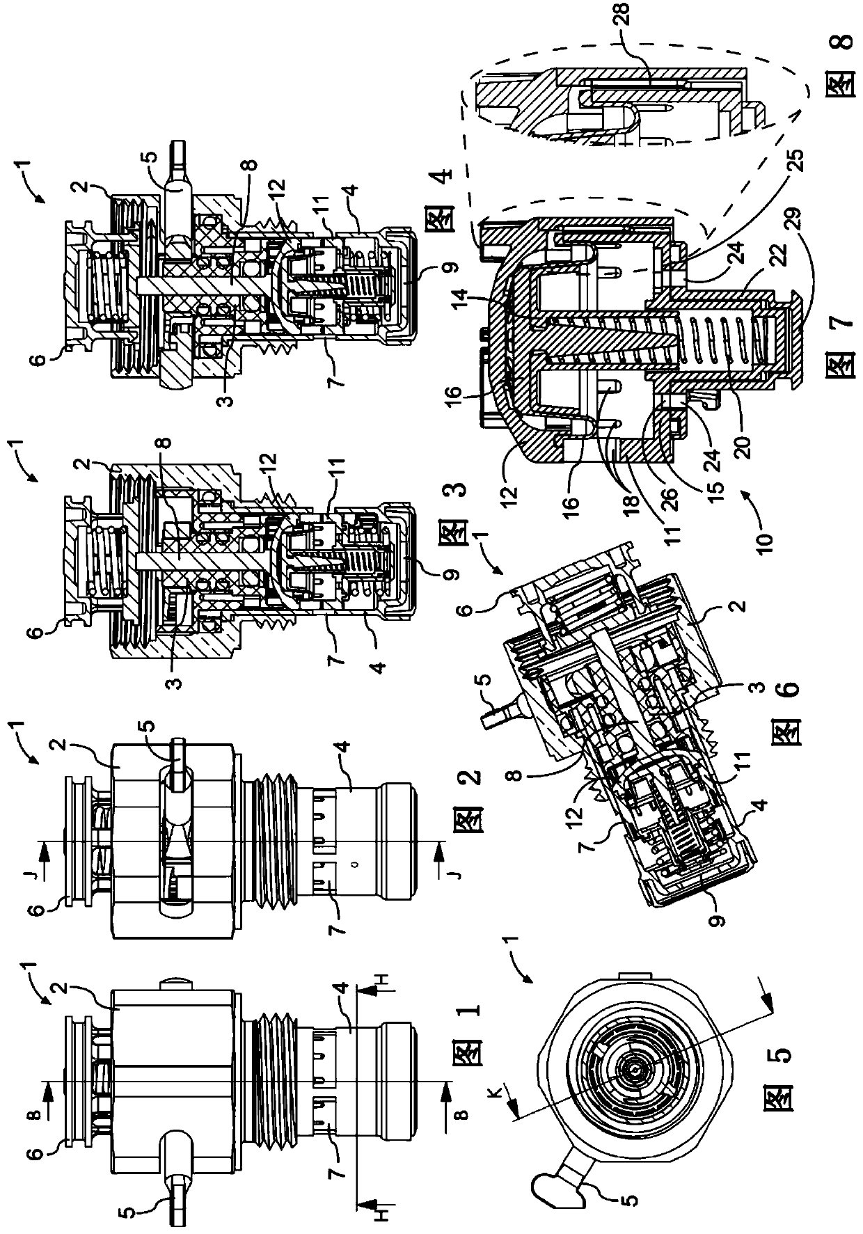
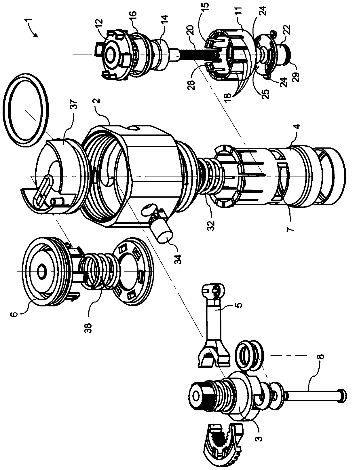
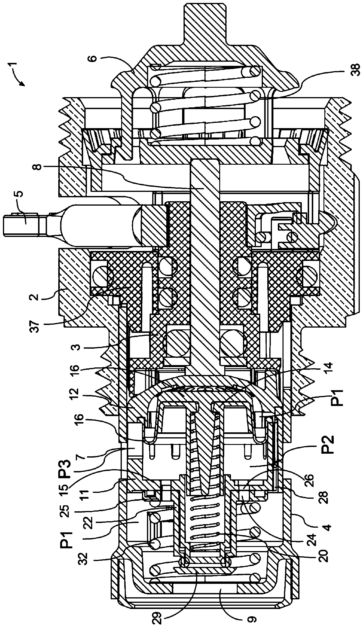
[0093] Reference Figure 1 to Figure 15 Describe the control valve. The control valve 1 includes a valve body 2. The valve body 2 is generally rotationally symmetric, and includes a part having a hexagonal outer contour and a cylindrical part 4. It should be noted, however, that the part having a hexagonal column type (order: column type) does not necessarily have a hexagonal outer shape, and other suitable shapes familiar to those skilled in the art, such as, for example, a simple columnar shape.

[0094] The valve body 2 is provided with a thread at or near one of its longitudinal ends for coupling with a linear actuator provided with a corresponding thread, such as an electric actuator (not shown). The valve body 2 is also provided with threads for threaded engagement with a housing or a body such as a manifold 40. Both the cylindrical part 4 and the part with a hexagonal exterior have a hollow interior in which most of the components of the control valve 1 are arranged.

[0...


PUM


Abstract

A control valve (1) for controlling flow of liquid in a heating and / or cooling installation with a pressure regulating arrangement for maintaining a constant differential pressure between a first pressure (PI) and a second pressure (P2) in the control valve ( 1). A movable throttle member (16) is urged to increase or decrease the flow resistance. The movable throttle member comprises a rolling diaphragm (16) that interacts with a plurality of exit openings (18) formed radially through the annular body (11). The rolling diaphragm (16) has a circular circumference attached to an annular body (11) that is arranged in the control valve (1). At least one pressure communication channel (28) extends in said annular body (11) for communicating the differential pressure P1 / P2 in the control valve (1). A manifold (40) for a heating system comprises a plurality of sockets (42) and a plurality of flow control valves (1) with a pressure regulating arrangement for maintaining a substantially constant differential pressure in the control valve (1). A floor heating system comprising the manifold (40).

Description

Technical field [0001] The present disclosure relates to a control valve including a pressure difference control function, and in particular to a control valve for controlling fluid in heating and / or cooling facilities such as buildings, ships, or factories. The present disclosure also relates to manifolds with control valves for heating and / or cooling facilities of buildings, ships, or factories, and to heating and / or cooling facilities of buildings, ships, or factories. Background technique [0002] The building is provided with a heating and / or cooling system (HVAC) comprising a plurality of separate circuits, each of which requires a flow of heating or cooling liquid through the separate circuit involved. The individual circuits can be: a circuit in a floor heating system that covers a specific area, a circuit in a sealed refrigeration system that covers a specific area, a circuit that includes one or more space radiators, and a combination of the above. Even for relatively ...

Claims


Application Information

Patent Timeline
Patent Type & Authority Applications(China)
IPC IPC(8): F16K3/32F24D3/00F24D19/10G05D7/01
CPCF24D19/1015F24D2220/0264G05D16/028G05D16/0658F24D3/1066
Inventor 比亚恩·维滕多夫·易卜生卡斯滕·恩瑟·米勒
Owner FLOWCON INT
Why Eureka
Try Eureka