Multi-dimensional phase change radiator and manufacturing method thereof
A manufacturing method and radiator technology, which are applied in the direction of modification by conduction heat transfer, cooling/ventilation/heating modification, modification with liquid cooling, etc. Large size and other problems, to achieve the effect of reducing weight, controllable cost, and good heat dissipation effect
Pending Publication Date: 2020-04-17
上海合辰科新材料有限公司
View PDF0 Cites 6 Cited by
- Summary
- Abstract
- Description
- Claims
- Application Information
AI Technical Summary
Problems solved by technology
[0007] However, the existing natural convection heat transfer and heat dissipation capabilities are poor, and the heat exchange coefficient of conventiona
Method used
View moreImage
Smart ImageViewing Examples

Examples
 PUM
| Property | Measurement | Unit |
|---|---|---|
| Thickness | aaaaa | aaaaa |
| Thickness | aaaaa | aaaaa |
| Spacing | aaaaa | aaaaa |
Abstract
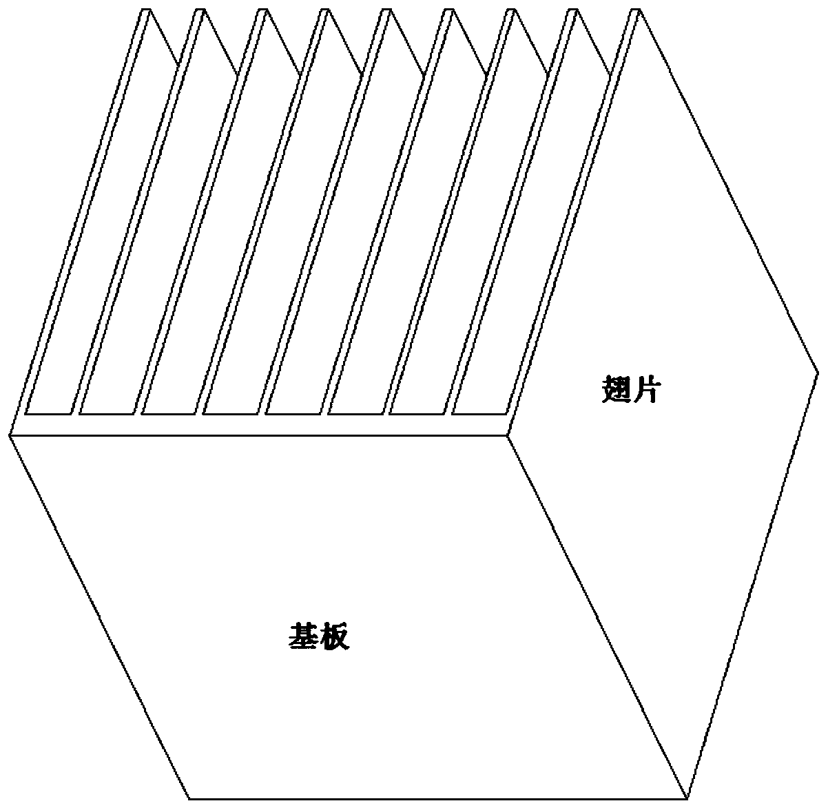
The invention relates to a multi-dimensional phase change radiator which comprises a radiator front side plate located in an XOY plane and a first set of fins vertically extending from the radiator front side plate to the Z direction at intervals. A plurality of second sets of fins are arranged at intervals in the direction perpendicular to the first sets of fins; the first sets of fins and the second sets of fins are crisscrossed; in the first set of fins, at least part of the fins are phase-change fins, and phase-change steam channels are formed in the phase-change fins; a phase-change baseplate is fixed to the outer side of a front side plate of the radiator, a base plate phase-change steam cavity is communicated with all fin phase-change steam channels to form a continuous closed vacuum environment, and a certain amount of phase-change working medium is placed in the continuous closed vacuum environment. The invention mainly aims at a natural convection radiator, the radiator greatly improves the heat dissipation efficiency and uniformity, greatly reduces the weight of the radiator, and reduces the volume of the radiator under the same heat dissipation boundary; the radiator is compact in structure, regular in shape, attractive in appearance and particularly suitable for heat dissipation of communication electronics, industrial transmission frequency conversion, inversionequipment and electronic components.
Description
Technical field [0001] The invention relates to a heat sink, in particular to a multi-dimensional phase change heat sink and a manufacturing method thereof. Background technique [0002] Along with the needs of the computer, communications, military and industrial electronics markets, electronic technology has developed rapidly, especially for electronic chips according to Moore's Law (the chip industry doubles the number of integrated crystals on the product every 18 to 24 months. )improve dramatically. So we see the fact: ①The packaging density of electronic devices continues to increase, and its heat flux density continues to increase; ②Electronic products continue to develop in the direction of miniaturization, with greater power and shrinking dimensions; ③Electronic products have penetrated In various fields, the application environment continues to expand, and the thermal environment used varies greatly. These development trends of electronic products have made the proble...
Claims
Login to View More Application Information
Patent Timeline
 IPC IPC(8): H05K7/20B23P15/26
CPCB23P15/26H05K7/2029H05K7/2039
Inventor 孟劲功孟观辰
Owner 上海合辰科新材料有限公司
Features
- R&D
- Intellectual Property
- Life Sciences
- Materials
- Tech Scout
- Unparalleled Data Quality
- Higher Quality Content
- 60% Fewer Hallucinations
Learn More Browse by: Latest US Patents, China's latest patents, Technical Efficacy Thesaurus, Application Domain, Technology Topic, Popular Technical Reports.
© 2025 PatSnap. All rights reserved.Legal|Privacy policy|Modern Slavery Act Transparency Statement|Sitemap|About US| Contact US: help@patsnap.com