Reinforced industrial switch
A technology of industrial switches and switches, applied in data exchange networks, digital transmission systems, electrical components, etc., can solve the problems of not being able to know the circuit of industrial switches, not being able to strengthen heat dissipation of industrial switches, and being unable to solve the problems of excessive heat of switches, etc., to achieve convenience The effect of heat dissipation, simple structure and diversified functions
- Summary
- Abstract
- Description
- Claims
- Application Information
AI Technical Summary
Problems solved by technology
Method used
Image

Examples
Embodiment 1
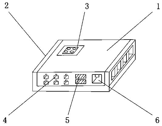
[0019] Such as figure 1 As shown, a reinforced industrial switch includes a switch main body 1, an induction mechanism 3 is arranged on the outer surface of the upper end of the switch main body 1, a reinforcement mechanism 2 is arranged on one side outer surface of the switch main body 1, and a front end outer surface of the switch main body 1 is arranged There are a network cable interface 4 , a card slot 5 and a power interface 6 , the network cable interface 4 is located on one side of the card slot 5 , and the power interface 6 is located on the other side of the card slot 5 .
Embodiment 2
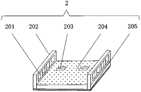
[0021] On the basis of Embodiment 1, such as figure 2 As shown, the reinforcing mechanism 2 includes a heat dissipation port 201, a switch fixing plate 202, a connecting groove 203, a heat-absorbing paint 204 and an anti-skid pad 205, and the outer surface of the upper end of the reinforcing mechanism 2 is provided with a connecting groove 203 and a heat-absorbing paint 204, and the connecting groove 203 Located on one side of the heat-absorbing paint 204, the outer surface of one side of the reinforcement mechanism 2 is provided with a heat dissipation port 201 and the switch fixing plate 202, the heat dissipation port 201 is located on one side of the switch fixing plate 202, and the outer surface of the lower end of the reinforcement mechanism 2 is provided with an anti-skid The pad 205 is convenient for the reinforcement mechanism 2 to reinforce and protect the switch main body 1 .
Embodiment 3
[0023] On the basis of Example 2, such as figure 2 As shown, a fixing buckle is provided between the reinforcement mechanism 2 and the switch fixing plate 202, and one side outer surface of the reinforcement mechanism 2 is fixedly connected to one side outer surface of the switch fixing plate 202 through the fixing buckle, and the heat dissipation port 201 is fixed to the switch. A fixing groove is provided between the plates 202, and one side of the outer surface of the heat dissipation port 201 is fixedly connected to one side of the outer surface of the switch fixing plate 202 through the fixing groove. The upper outer surface of the upper end of the reinforcement mechanism 2 is fixedly connected with the outer surface of one side of the connecting groove 203 through a buckle, and a fixing glue is provided between the reinforcement mechanism 2 and the heat-absorbing paint 204, and the upper end outer surface of the reinforcement mechanism 2 is connected by the fixing glue a...
PUM
 Abstract
Description
Claims
Application Information
 - Generate Ideas
- Intellectual Property
- Life Sciences
- Materials
- Tech Scout
- Unparalleled Data Quality
- Higher Quality Content
- 60% Fewer Hallucinations
Browse by: Latest US Patents, China's latest patents, Technical Efficacy Thesaurus, Application Domain, Technology Topic, Popular Technical Reports.
© 2025 PatSnap. All rights reserved.Legal|Privacy policy|Modern Slavery Act Transparency Statement|Sitemap|About US| Contact US: help@patsnap.com