


Quick Research
Generate reliable direction feasibility study reports for your R&D in just a few steps.

Technical Q&A
Discover and master advanced knowledge NOW. Basics, ideas, possibilities, all at once.

Find Solutions
As an expert in R&D theories, this can generate solutions to your technical problems instantly.

Evaluate Feasibility
Analyze your overall solution with one click, know your potential R&D risks in advance.

Monitor Landscape
Get weekly tech updates, stay abreast of the latest tech innovations and key insights.
Combined type cut-off device and pipeline equipped with same
A shut-off device and combined technology, which is applied in the direction of valve devices, pipe components, pipes/pipe joints/pipe fittings, etc., can solve the problem of large deformation of rubber sleeves, poor sealing of pressurized chambers, and limited diameter of rubber sleeves and other problems, to achieve the effect of simple structure, fast response, high safety and reliability
- Summary
- Abstract
- Description
- Claims
- Application Information
AI Technical Summary
Problems solved by technology
Method used
Image

Examples
Embodiment 1
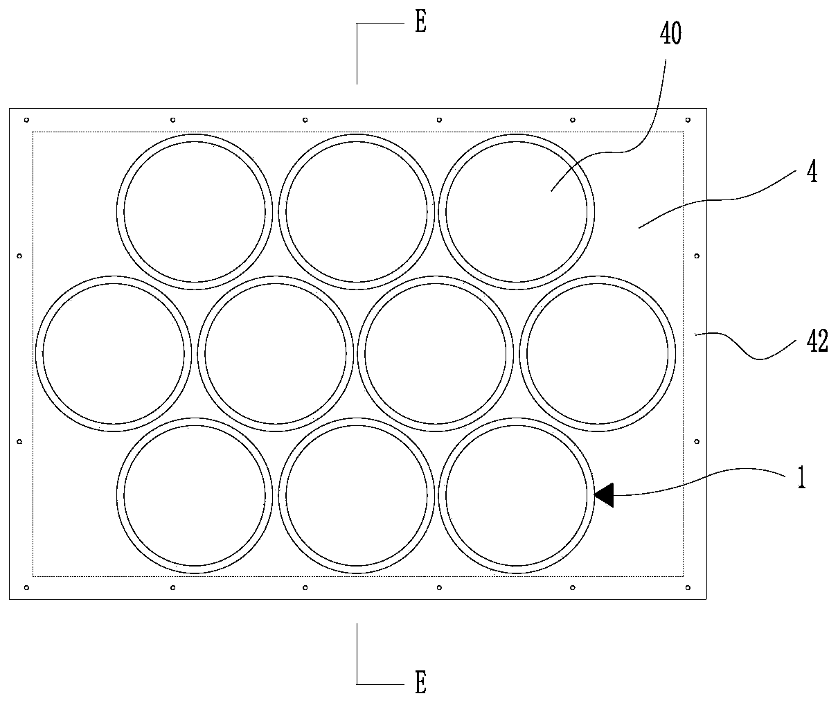
[0048] see Figure 1 to Figure 4 As shown, the present invention provides a combined shut-off device, comprising:
[0049] Mounting plate 4, several mounting holes 40 are opened on the mounting plate, and the mounting holes 40 are arranged horizontally and / or vertically, wherein the number and arrangement of the mounting ports 40 are designed according to the pipe diameter or the size of the opening of the discharge port in the use environment And the specifications of the installation port 40 are determined, see figure 1As shown, as a preferred solution, three horizontal rows of mounting holes 40 are arranged horizontally from top to bottom, and several mounting holes 40 are arranged in each horizontal row, and the centerlines of the mounting holes 40 of the same horizontal row are located on the same straight line, and two adjacent horizontal rows Rows of mounting holes 40 are arranged in a staggered manner, and more mounting holes 40 are arranged on the plane of the mounti...
Embodiment 2
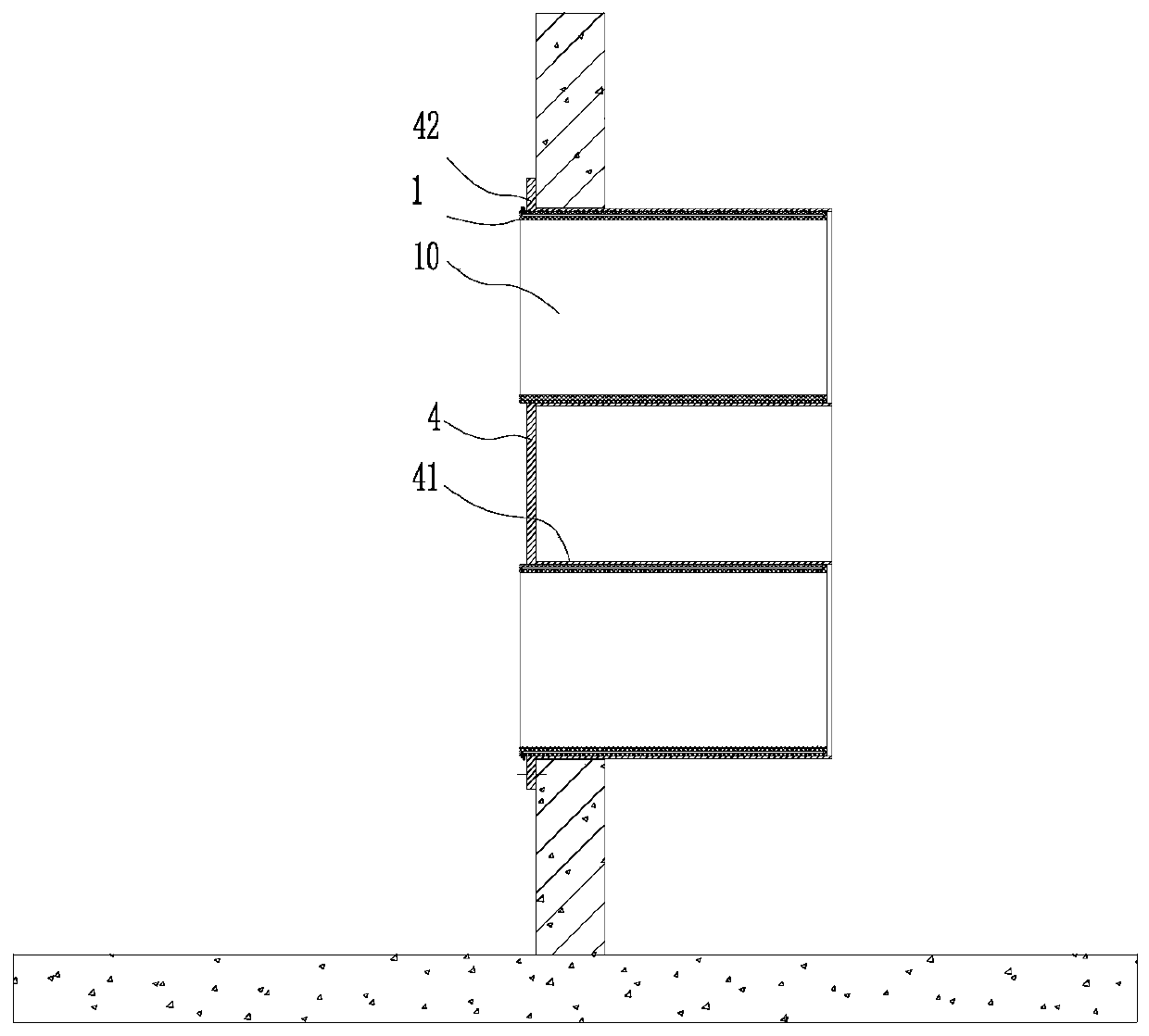
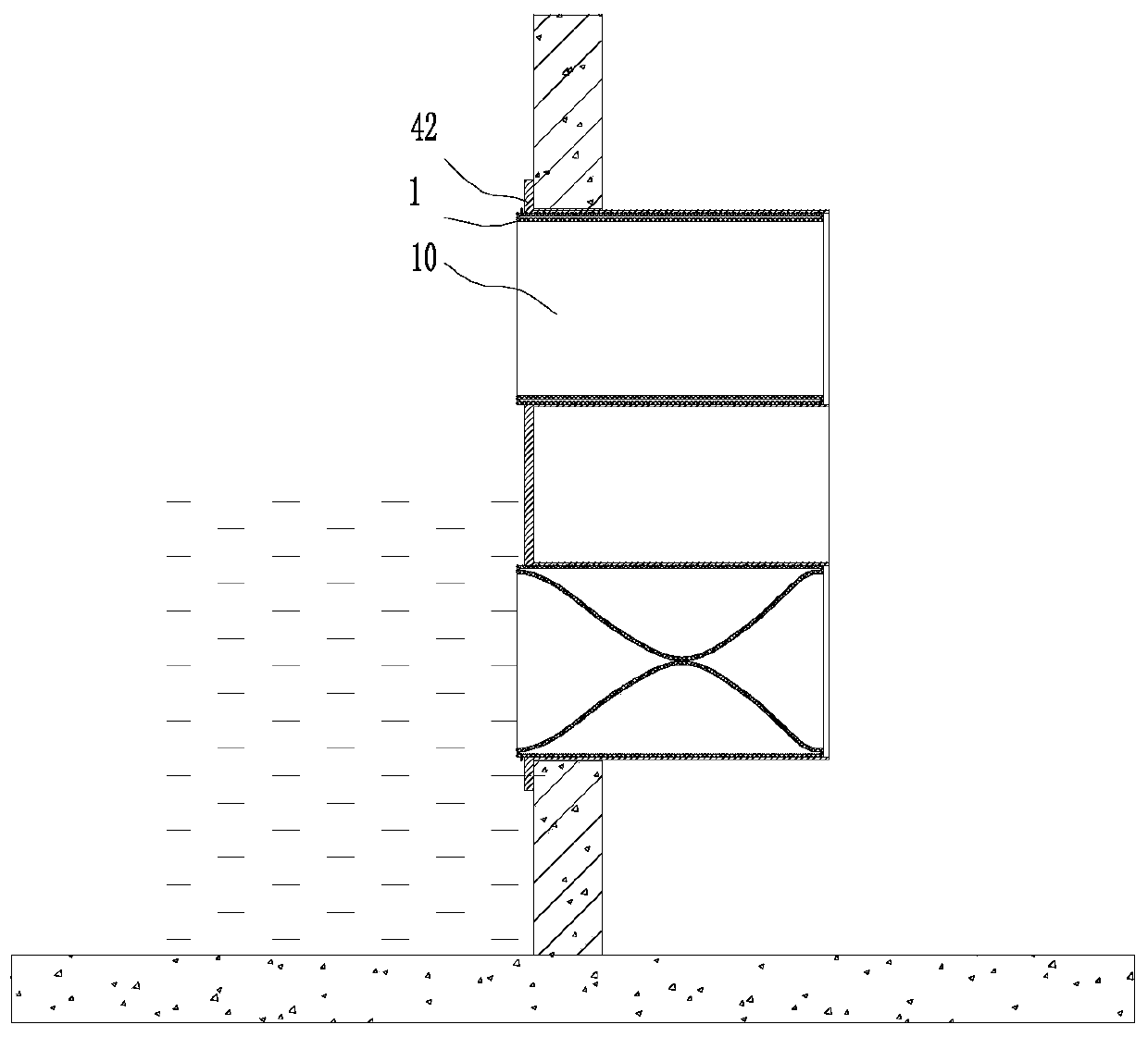
[0063] see image 3 and Figure 4 As shown, the present embodiment 2 provides a kind of pipeline or drain that is installed with intercepting device, comprises:
[0064] The combined shut-off device in the above-mentioned embodiment 1;
[0065] The installation plate 4 of the intercepting device is provided with a circumferential installation flange 42, and the installation flange is supported around the end of the pipe or the outlet, and the installation plate 4 is fixed around the pipe or the outlet by bolts, and the flow channel of the intercepting device 10 is communicated with pipeline or outlet.
[0066] In this embodiment, the combined intercepting device is provided with three horizontal rows of intercepting devices, each horizontal row is equipped with several intercepting devices, and the centerlines of the circulation passages 10 of each horizontal row are located on the same straight line, wherein each horizontal row of intercepting devices passes through The sa...
PUM
 Abstract
Description
Claims
Application Information
 - R&D Engineer
- R&D Manager
- IP Professional
- Industry Leading Data Capabilities
- Powerful AI technology
- Patent DNA Extraction
Browse by: Latest US Patents, China's latest patents, Technical Efficacy Thesaurus, Application Domain, Technology Topic, Popular Technical Reports.
© 2024 PatSnap. All rights reserved.Legal|Privacy policy|Modern Slavery Act Transparency Statement|Sitemap|About US| Contact US: help@patsnap.com