


Quick Research
Generate reliable direction feasibility study reports for your R&D in just a few steps.

Technical Q&A
Discover and master advanced knowledge NOW. Basics, ideas, possibilities, all at once.

Find Solutions
As an expert in R&D theories, this can generate solutions to your technical problems instantly.

Evaluate Feasibility
Analyze your overall solution with one click, know your potential R&D risks in advance.

Monitor Landscape
Get weekly tech updates, stay abreast of the latest tech innovations and key insights.
Hydraulic pressure displacement injection pump
A technology for injecting pumps and hydraulic pressure, applied in pumps, pump control, piston pumps, etc., can solve the problems of short service life of reversing electronic components, and achieve the effects of long service life, low manufacturing cost and reliable equipment guarantee
- Summary
- Abstract
- Description
- Claims
- Application Information
AI Technical Summary
Problems solved by technology
Method used
Image

Examples
Embodiment 1
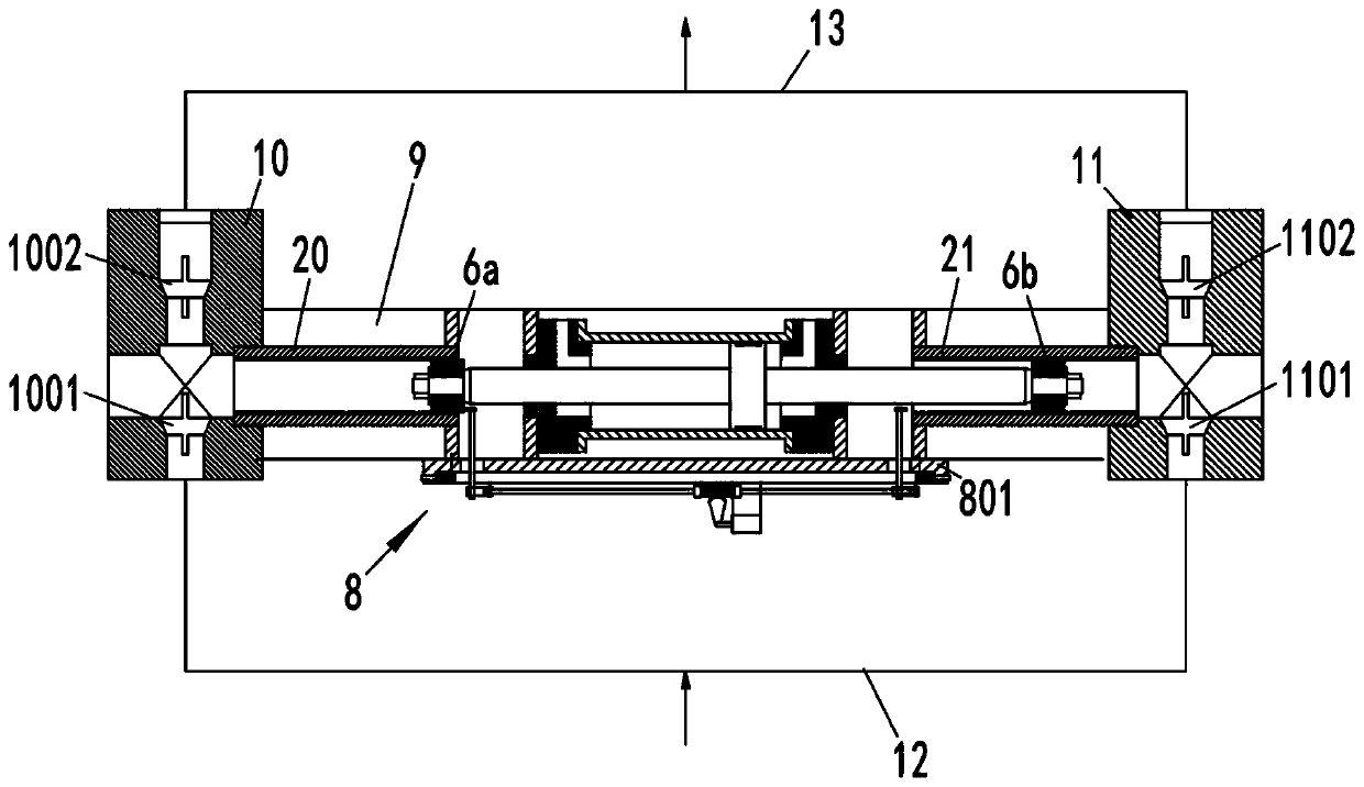
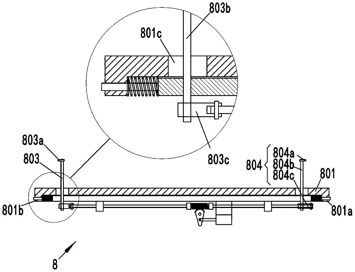
[0041] image 3 A schematic diagram of the working principle of the reversing control unit 8 in the hydraulic pressure-driven injection pump according to an embodiment of the present invention and its enlarged view are illustrated. Figure 4 A schematic diagram of the first state of the reversing control unit 8 in the hydraulic pressure-driven injection pump according to an embodiment of the present invention is illustrated. Figure 5 A schematic diagram of the second state of the reversing control unit 8 in the hydraulic pressure-driven injection pump according to an embodiment of the present invention is illustrated.
[0042] Such as Figures 3 to 5 As shown, the hydraulic pressure-driven injection pump of this embodiment includes a reversing control unit 8, and the reversing control unit 8 is used to control the piston rod 502 to switch the movement direction at the stroke end of the piston rod 502. The reversing control unit 8 includes a first trigger 803 , a second trig...
Embodiment 2
[0052] This embodiment is further improved on the basis of Embodiment 1. During the continuous operation of the pressure-driven injection pump, due to the sticking of the spool of the hydraulic valve or other reasons, there is a possibility of reversing failure.
[0053]In the hydraulic pressure-driven injection pump of this embodiment, the reversing control unit 8 further includes a fixed bracket 801 and a floating bracket 802 . The fixed frame 801 is fixedly connected with the frame 9 , and the floating bracket 802 is horizontally slidably connected with the fixed frame 801 . The first rotating shaft 803b is rotatably connected to the floating bracket 802 , and the second rotating shaft 804b is rotatably connected to the floating bracket 802 . Two ends of the floating bracket 802 are respectively connected to the fixed frame 801 through support springs 810 . The swing gear 807 is rotatably connected to the floating bracket 802 , and the connecting rod 805 is horizontally s...
Embodiment 3
[0058] In the middle of two consecutive commutations, the commutation control unit 8 needs to maintain the position. In order to meet the above requirements, this embodiment is further improved on the basis of embodiment 1.
[0059] Such as Figure 6 and Figure 7 As shown, in this embodiment, the swing gear 807 further includes an arc-shaped protrusion 807d, and the arc-shaped protrusion 807d is located at the opposite end of the tooth-shaped portion 807a. Specifically, the swing gear 807 is sequentially provided with a toothed portion 807a, a supporting hole 807b, a slide groove 807c and an arc-shaped protrusion 807d.
[0060] The reversing control unit 8 further includes a limit assembly 808, and the limit assembly 808 includes a housing 808a, a sliding rod 808b, a roller 808c and a limit support spring 808d. The housing 808a is fixedly connected with the floating bracket 802 . The sliding rod 808b is slidably connected to the housing 808a. One end of the limit support...
PUM
 Abstract
Description
Claims
Application Information
 - R&D Engineer
- R&D Manager
- IP Professional
- Industry Leading Data Capabilities
- Powerful AI technology
- Patent DNA Extraction
Browse by: Latest US Patents, China's latest patents, Technical Efficacy Thesaurus, Application Domain, Technology Topic, Popular Technical Reports.
© 2024 PatSnap. All rights reserved.Legal|Privacy policy|Modern Slavery Act Transparency Statement|Sitemap|About US| Contact US: help@patsnap.com