
Winding equipment for textile machine

A technology of textile machinery and equipment, applied in the field of winding equipment that can supply empty winding tubes, can solve problems such as low workability

Active Publication Date: 2020-04-17
OERLIKON TEXTILE GMBH & CO KG
View PDF18 Cites 1 Cited by
  • Summary
  • Abstract
  • Description
  • Claims
  • Application Information

AI Technical Summary

Problems solved by technology

The setting method of the supply mechanism described in EP2002006845 is not suitable for solving the aforementioned problem of low workability

Method used


Image

  • Winding equipment for textile machine
  • Winding equipment for textile machine
  • Winding equipment for textile machine

Examples


Embodiment Construction

[0065] The details of the present invention can be understood more clearly with reference to the accompanying drawings and the description of specific embodiments of the present invention. However, the specific embodiments of the present invention described here are only for the purpose of explaining the present invention, and should not be construed as limiting the present invention in any way. Under the teaching of the present invention, the skilled person can conceive any possible modification based on the present invention, and these should be regarded as belonging to the scope of the present invention. It should be noted that when an element is referred to as being “disposed on” another element, it may be directly on the other element or there may also be an intervening element. When an element is referred to as being "connected to" another element, it can be directly connected to the other element or intervening elements may also be present. The terms "mounted", "connec...


PUM


Abstract

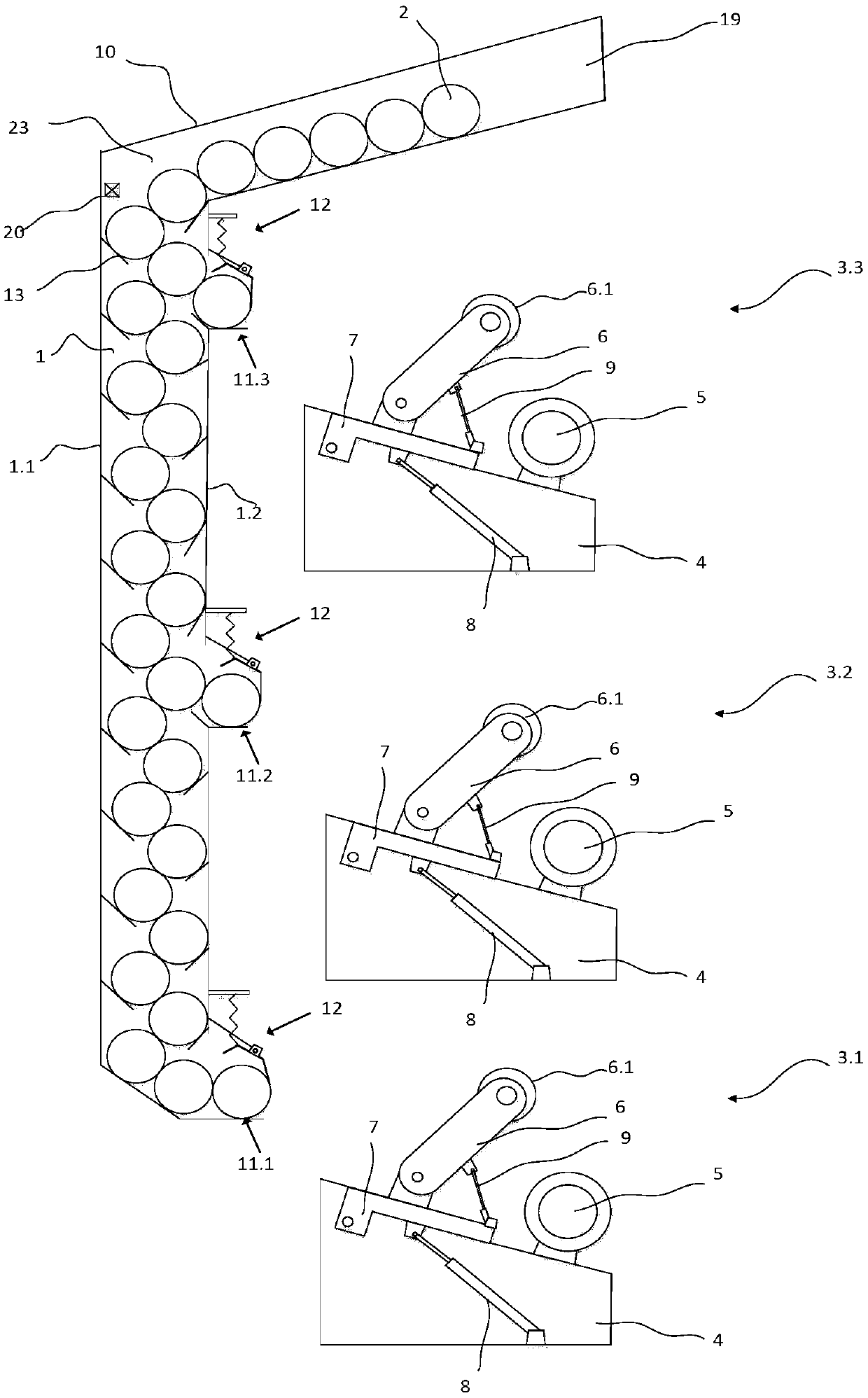
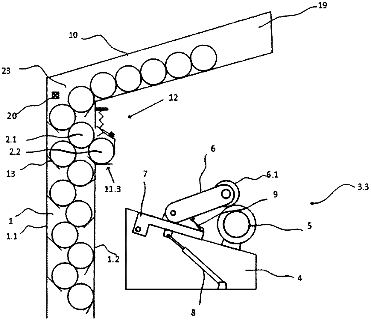
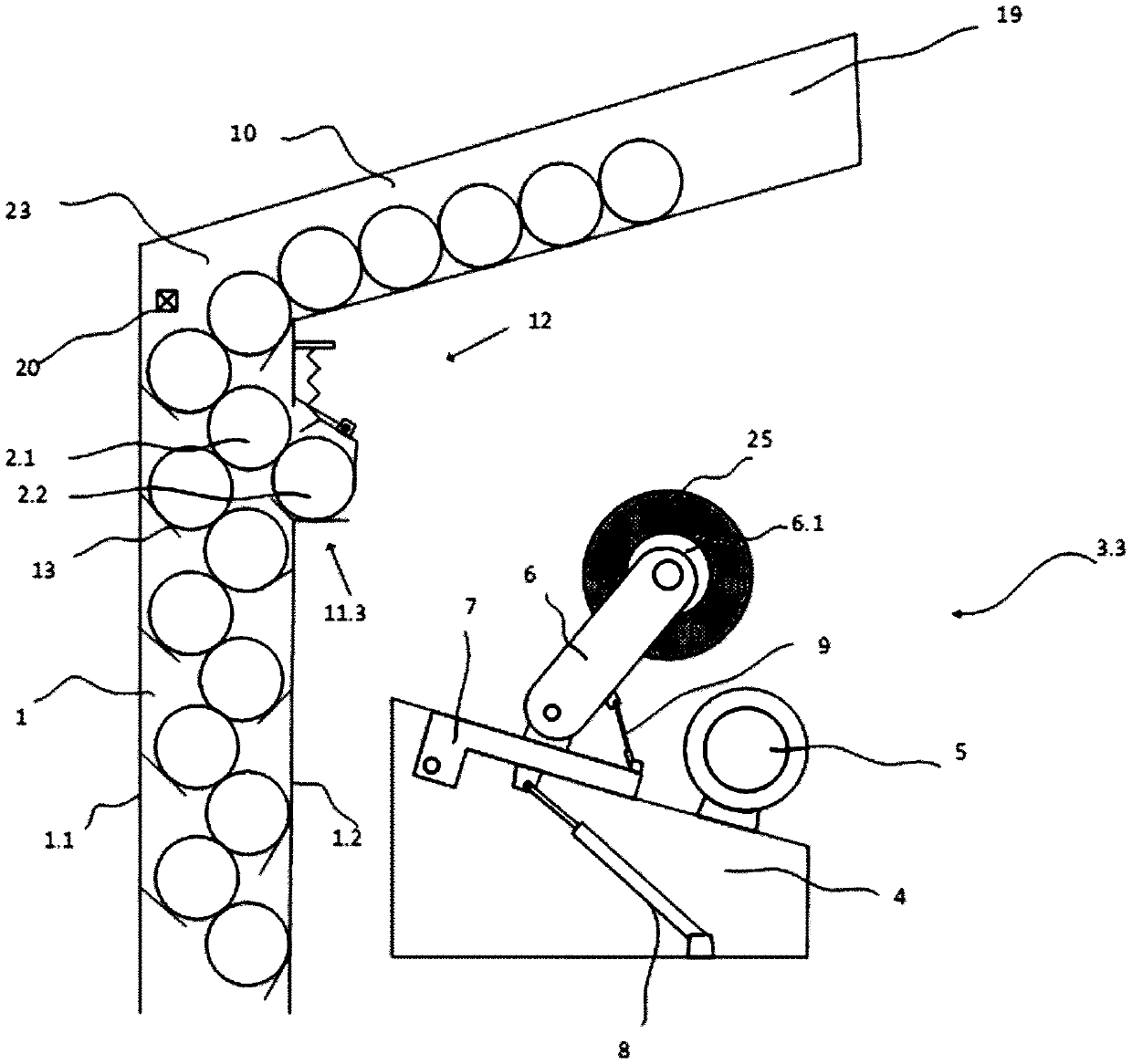
The invention discloses winding equipment for a textile machine. The winding equipment is provided with a plurality of multilayer-stacked winding devices, and a supply mechanism holding winding pipeswaiting for being supplied. Each winding device is provided with a rotatable rocking frame, a driving roller capable of driving the winding pipes to rotate, and a yarn guide mechanism used for guidingyarn. The supply mechanism comprises a pipe bin with a winding pipe centralized inlet. The pipe bin is arranged in the stacked direction and supplies the winding pipes to the multilayer winding devices in a centralized mode. The winding pipe centralized inlet of the supply mechanism allows the winding pipes needed by the multilayer winding devices to be put in through one inlet in a centralized mode, and the complexity of winding pipe put-in operation is lowered compared with that of the prior art in which each layer of winding pipes are put in separately.

Description

technical field [0001] The invention relates to a winding device of a textile machine, in particular to a winding device capable of supplying empty winding tubes. Background technique [0002] The winding equipment of textile machinery is usually composed of several winding devices. These winding devices are stacked vertically in multiple layers and placed side by side horizontally. Each winding device is used as an independent unit to form and wind one or two yarns, and replace the wound bobbins with empty winding tubes. Each winding device comprises a cradle, a drive roller, a yarn guiding mechanism and a supply mechanism accommodating a winding tube. [0003] Such a winding device is disclosed in EP2002006845, wherein the yarn guiding mechanism is located upstream of the drive roller with reference to the advancing direction of the yarn. [0004] EP2002006845 specifically discloses that each winding device is equipped with a separate supply mechanism. Winding tubes ar...

Claims


Application Information

Patent Timeline
Patent Type & Authority Applications(China)
IPC IPC(8): B65H67/04
CPCB65H67/0405B65H2701/31B65H67/0417B65H67/068
Inventor 姜华吴天成
Owner OERLIKON TEXTILE GMBH & CO KG
Learn More