
A continuous loading punch automatic feeding device

A technology of feeding device and punching machine, which is applied in the field of automatic feeding device for punching machines, can solve problems such as workers’ life safety not being guaranteed, damage to stamping blocks, and impact on stamping quality, so as to avoid workers’ life and health hazards, protect equipment from damage, and improve equipment quality. The effect of service life

Active Publication Date: 2021-04-06
CHENGDU TECH UNIV +1
View PDF6 Cites 0 Cited by
  • Summary
  • Abstract
  • Description
  • Claims
  • Application Information

AI Technical Summary

Problems solved by technology

[0003] However, the traditional punching machine needs to be manually fed. Improper operation will cause major accidents to skilled workers, and the safety of workers cannot be guaranteed. Moreover, when the processing materials are damaged during lathe feeding, it is difficult to manually identify them all and remove them in time. Damaged processing materials Not only is it easy to affect the stamping quality, but some irregularly shaped processing materials will also damage the stamping block. For this purpose, an automatic feeding device for punching machines that can be continuously loaded is designed.

Method used


Image

  • A continuous loading punch automatic feeding device
  • A continuous loading punch automatic feeding device
  • A continuous loading punch automatic feeding device

Examples


Embodiment Construction

[0030] The following will clearly and completely describe the technical solutions in the embodiments of the present invention with reference to the accompanying drawings in the embodiments of the present invention. Obviously, the described embodiments are only some, not all, embodiments of the present invention. Based on the embodiments of the present invention, all other embodiments obtained by persons of ordinary skill in the art without making creative efforts belong to the protection scope of the present invention.

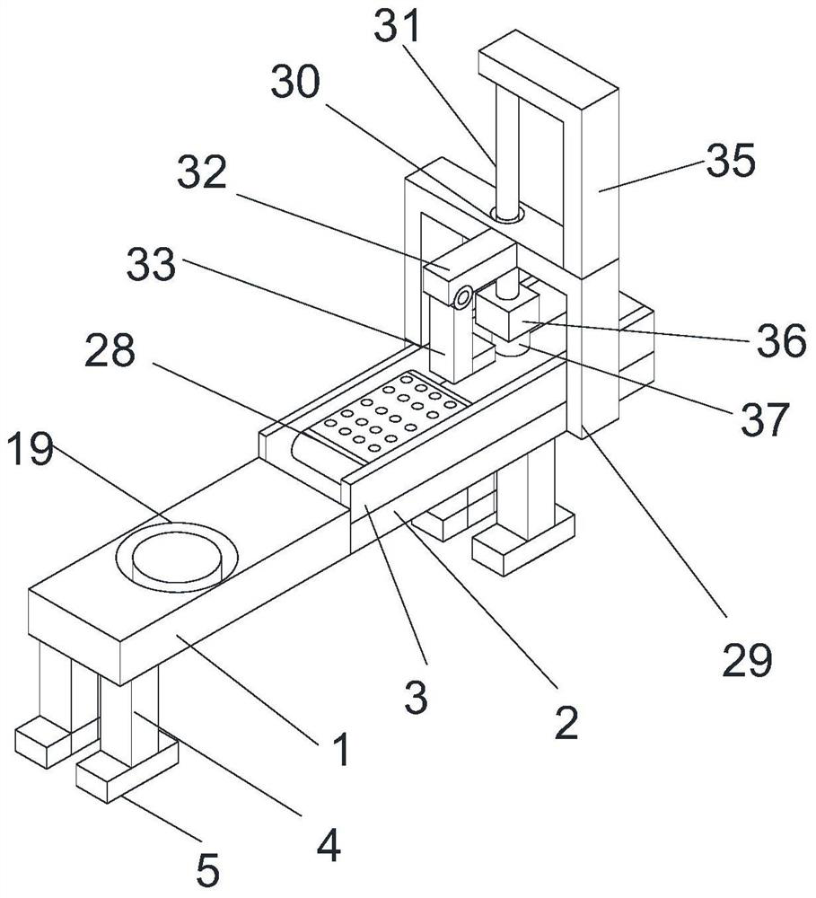
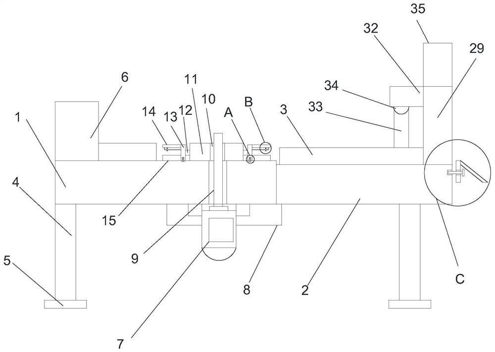
[0031] see Figure 1-9 , the present invention provides a technical solution: a continuous loading punch automatic feeding device, including a feeding table 1, the feeding table 1 is a rectangular structure, the rear of the feeding table 1 is provided with a punching table 2, the punching Table 2 is a rectangular structure, the height of the stamping table 2 is three-quarters of the feeding table 1, the front wall of the stamping table 2 is fixedly connected t...


PUM


Abstract

The invention discloses an automatic feeding device for a punch press that can be continuously loaded, and relates to the technical field of punch press equipment. The continuously loadable punch automatic feeding device includes a feeding table, the feeding table is a rectangular structure, a punching table is arranged behind the feeding table, the punching table is a rectangular structure, and the height of the punching table is three quarters of the feeding table. The front wall of the feeding table is fixedly connected to the rear wall of the feeding table, and two stamping baffles are arranged above the stamping table. In the present invention, by setting the rolling groove, when the motor drives the rotating disc to rotate, the rotating disc drives the rotating column to rotate, and the rotating column drives the rotation. The plate rotates, and the rotating plate drives the wheels inside the car groove to rotate in the groove of the rolling groove. The wheels reduce the friction between the rotating plate and the surface of the feeding table, reduce the kinetic energy loss of the motor, save a lot of power when the equipment runs for a long time, and protect the rotation. The friction between the plate and the feeding table causes damage to the equipment and increases the service life of the equipment.

Description

technical field [0001] The invention relates to the technical field of punch press equipment, in particular to an automatic feeding device for punch presses capable of continuous loading. Background technique [0002] A punch press is a stamping press. In national production, the stamping process has the advantages of saving materials and energy, high efficiency, low technical requirements for operators, and the ability to produce products that cannot be achieved by mechanical processing through various mold applications. It is used more and more widely, and stamping production is mainly for plates. Through the mold, blanking, punching, forming, deep drawing, trimming, fine blanking, shaping, riveting and extrusion parts can be made, which are widely used in various fields. For example, we use switch sockets, cups, cupboards, dishes, computer cases, and even missile aircrafts. There are many accessories that can be produced by punching through molds. [0003] However, the...

Claims


Application Information

Patent Timeline
Patent Type & Authority Patents(China)
IPC IPC(8): B21D43/14B21D43/12B21C51/00B07C5/34B07C5/36B21D45/02
CPCB07C5/34B07C5/36B21C51/00B21D43/026B21D43/12B21D43/14B21D45/02
Inventor 张博尹良君云忠源颜晓东曹铭浩
Owner CHENGDU TECH UNIV
Learn More