
Portable live working bypass equipment

A technology for live operation and bypass equipment, applied in the direction of overhead line/cable equipment, etc., can solve the problems of high cost of intelligence, complicated replacement methods, etc., and achieve the effect of simple structure, convenient installation and setting, and improved disassembly efficiency.

Inactive Publication Date: 2020-04-14
WENZHOU ELECTRIC POWER BUREAU +1
View PDF8 Cites 2 Cited by
  • Summary
  • Abstract
  • Description
  • Claims
  • Application Information

AI Technical Summary

Problems solved by technology

[0003] The purpose of the present invention is to provide a portable bypass device for live work, which can effectively solve the problems of high cost and complicated replacement methods of the existing bypass operation without power failure

Method used


Image

  • Portable live working bypass equipment
  • Portable live working bypass equipment
  • Portable live working bypass equipment

Examples


Embodiment Construction

[0026] Embodiments of the invention are described in detail below, examples of which are illustrated in the accompanying drawings. The embodiments described below by referring to the figures are exemplary and are intended to explain the present invention and should not be construed as limiting the present invention.

[0027] In describing the present invention, it should be understood that the terms "center", "longitudinal", "transverse", "length", "width", "thickness", "upper", "lower", "front", " The orientation or positional relationship indicated by "rear", "left", "right", "vertical", "horizontal", "top", "bottom", "inner" and "outer" are based on the orientation or position shown in the drawings The positional relationship is only for the convenience of describing the present invention and simplifying the description, but does not indicate or imply that the referred device or element must have a specific orientation, be constructed and operated in a specific orientation,...


PUM


Abstract

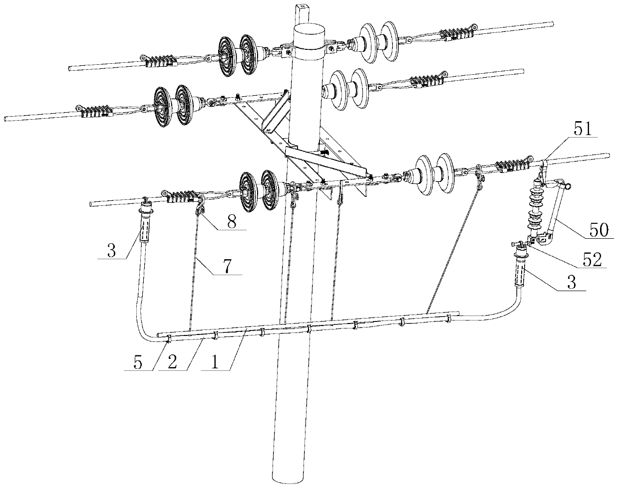
The invention discloses portable live working bypass equipment. The equipment comprises a cable insulation hanging rod, an insulation hook and a drop-out fuse. The cable insulation hanging rod is hungon the insulation hook, and one end of the cable insulation hanging rod is connected with the drop-out fuse. The equipment has advantages that a pole-mounted intelligent switch is replaced by new equipment; bypass building can be completed only through one operation vehicle, original equipment needs two operation vehicles, new equipment only needs to hang a set of special drop-out fuses, leads and lead fixing cross arms, and weight is much lighter than that of original bypass switches and leads; and expense cost is reduced by at least 80%. A defect that time and labor are wasted when originalbypass operation is used for replacing the pole-mounted intelligent switch is overcome, and equipment procurement cost is greatly saved.

Description

technical field [0001] The invention relates to a portable bypass device for live work. Background technique [0002] With the increasing demand for power supply reliability, the application of smart switches is also increasing. In order to replace the smart switch on the pole without power failure, we are currently using the bypass operation method without power failure to replace the smart switch on the pole. However, it is cumbersome to use the existing bypass equipment to replace the intelligent switch on the pole. It is necessary to use the bypass switch, the insulating drain wire and the fixed cross-arm of the insulating drain wire to build a temporary bypass. After the bypass is connected, the smart switch is disconnected, and the The drainage wires on both sides are disconnected to realize the replacement of the intelligent switch. In this operation method, the operator needs to hoist the bypass switch and the lead wires of the bypass switch. The equipment is expen...

Claims


Application Information

Patent Timeline
IPC IPC(8): H02G1/02H02G1/04
CPCH02G1/02H02G1/04
Inventor 周波章文海毛益凉陈凌霄邱阳徐贤贵毛耀文陈坚周霞杨凯蔡铁骥黄新克王茜吴世军沈海华山建冬
Owner WENZHOU ELECTRIC POWER BUREAU
Learn More