A pull back door meter box
A technology for pull-back doors and watch boxes, which is applied in measuring devices, door/window accessories, and measuring electrical variables. It can solve problems such as box door deformation, watch box damage, and loss of unlocking devices, so as to achieve convenient opening and closing and improve service life. , Reduce the effect of forgetting to close the door and damage
- Summary
- Abstract
- Description
- Claims
- Application Information
AI Technical Summary
Problems solved by technology
Method used
Image
Examples
Embodiment 1
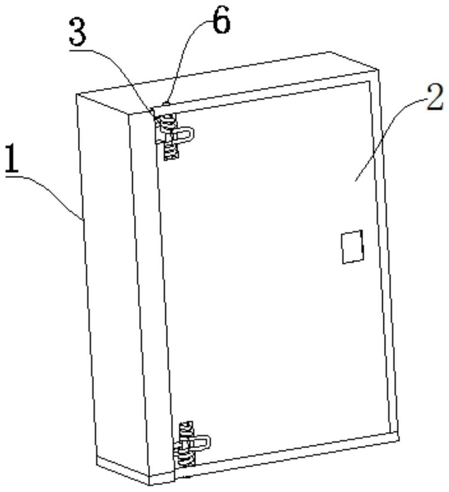
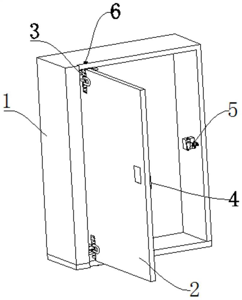
[0023] Example 1: as Figure 1 to Figure 2 As shown, the present invention provides a return door meter box, which is characterized in that it includes a box body 1, a box door 2 is arranged on the box body 1, and one side of the box door 2 is installed between the box body 1. There is a return spring 3, a lock rod 4 is provided on the inner wall of the other side of the box door 2, and a lock hook 5 is provided on the corresponding side of the box body 1 and the lock rod 4, and the lock hook 5 is adapted to the lock rod 4. The box body 1 is rotatably connected with the box body 1, and the box body 1 is also provided with a magnetic force unlocking assembly that drives the rotation of the lock hook 5. The box body 1 is also provided with a delayed door closing assembly.
[0024] The upper and lower ends of one side of the box door 2 are provided with a rotating pin 6 , the box door 2 is rotatably connected to the box body 1 through the rotating pin 6 , and the return spring 3 ...
Embodiment 2
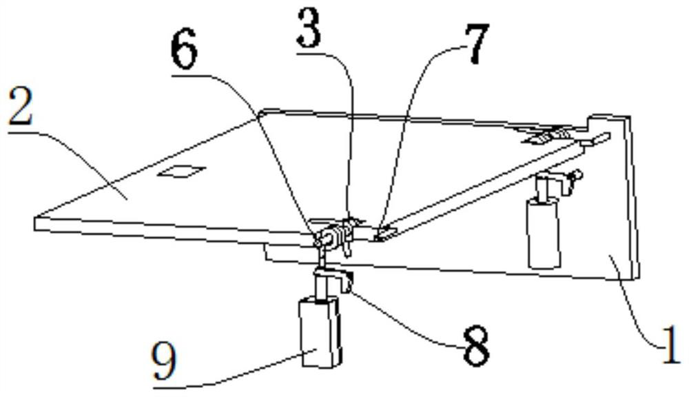
[0026] Embodiment 2: as Figure 3-6 As shown, on the basis of the first embodiment, a time-delayed door closing component is also arranged between the box body 1 and the box door 2 . The delayed door closing assembly includes a toggle rod 7, a rotating block 8 and a delay cylinder 9, the toggle rod 7 is fixedly arranged at the end of the box door 2, and the middle of the rotating block 8 rotates with the box body 1 through a pin shaft. Connection, the delay cylinder 9 is fixedly installed on the box 1, one end of the rotating block 8 is located at the front end of the delay cylinder 9, and the toggle rod 7 is adapted to the other end of the rotating block 8 to toggle the rotating block. 8 spins. The time delay cylinder 9 includes a cylinder barrel 91 and a telescopic rod 92. The front end of the telescopic rod 92 passes through the front end of the cylinder barrel 91. The rear end of the telescopic rod 92 is connected with a piston 93, and the piston 93 is connected to the cy...
Embodiment 3
[0029] Example three: as Figure 7-8As shown, the magnetic unlocking assembly includes a pressure spring 10 and an electromagnetic force block 11. One end of the pressure spring 10 is fixedly connected to the middle of the lock hook 5, and the other end of the pressure spring 10 is fixedly connected to the side wall of the box body 1. The The electromagnetic block 11 is installed on the side wall of the box body 1 corresponding to the front part of the lock hook 5 . The magnetic unlocking assembly further includes a magnetic unlocking controller, which is used to identify the unlocking signal and control the magnetic force of the electromagnetic force block 11 .
[0030] When the box door 2 is in the closed state, the pressure spring 10 is against the lock hook 5, so that the lock hook 5 hooks the lock rod 4 forward to complete the locking of the box door 2. The lock hook 5 is made of a material with magnetic attraction capability. such as iron. When it is necessary to open ...
PUM
 Abstract
Description
Claims
Application Information
 - Generate Ideas
- Intellectual Property
- Life Sciences
- Materials
- Tech Scout
- Unparalleled Data Quality
- Higher Quality Content
- 60% Fewer Hallucinations
Browse by: Latest US Patents, China's latest patents, Technical Efficacy Thesaurus, Application Domain, Technology Topic, Popular Technical Reports.
© 2025 PatSnap. All rights reserved.Legal|Privacy policy|Modern Slavery Act Transparency Statement|Sitemap|About US| Contact US: help@patsnap.com


