Circuit board universal fixture for vibration test board and using method thereof
A vibration test bench and circuit board technology, which is applied in vibration testing, machine/structural component testing, measuring devices, etc., can solve the problems of cost increase, detection cycle lengthening, and efficiency reduction, so as to reduce labor costs, Improved versatility and improved productivity
- Summary
- Abstract
- Description
- Claims
- Application Information
AI Technical Summary
Problems solved by technology
Method used
Image
Examples
Embodiment 1
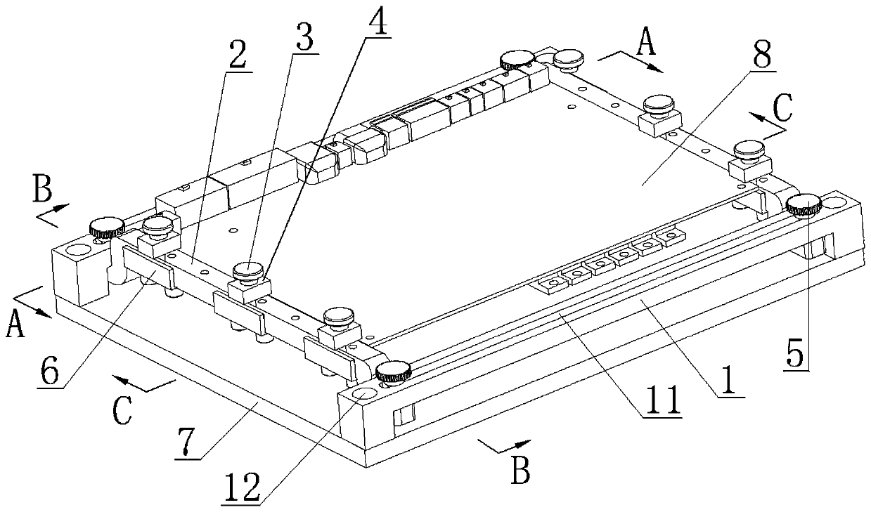
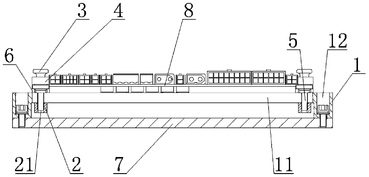
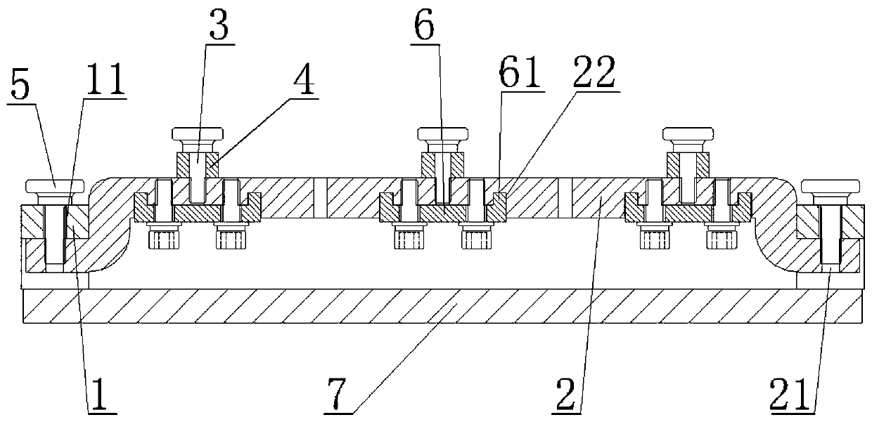
[0037] from Figure 1 to Figure 5 It can be seen that the circuit board universal fixture for the vibration test bench of the present invention is installed on the bottom plate 7 of the vibration test bench, including two limit bars 1, two movable bars 2, six compression screws 3, six pressure blocks 4, four Locking screw 5 and six lower limit blocks 6,
[0038] The limit bar 1 is in the shape of ㄇ as a whole, and the horizontal section in the middle of the limit bar 1 is milled with a longitudinal strip hole 11 running through the upper and lower sides, and the vertical section at both ends of the limit bar 1 is milled with mounting holes 12 that run through the upper and lower sides. Limiting strips 1 are installed horizontally on the front edge and the rear edge of the vibration test bench bottom plate 7 respectively through screws through the mounting holes 12, and the two limiting strips 1 are arranged in parallel front and back on the vibration test bench bottom plate 7;...
Embodiment 2
[0050] The difference between this embodiment and the first embodiment is that the cross-section of the movable bar 2 corresponding to the top and bottom of the pressing block 4 is an integrated convex structure, and the pressing block 4 and the movable bar 2 are both made of insulating materials.
[0051] The method for using the circuit board universal fixture for this vibration test bench of the present invention comprises the following steps:
[0052] S1, unscrew the locking screw 5, adjust the distance between the adjacent movable strips 2 according to the front and rear sides of the circuit board to be tested, so that the left and right sides of the circuit board to be tested are located directly above the bottom surface of the protruding part of the adjacent movable strip 2; Tighten the locking screw 5 to fix the left and right positions of the limit bar 2;
[0053] S2, unscrew the compression screw 3, turn the briquetting block 4 so that the short side of the briquetti...
PUM
 Abstract
Description
Claims
Application Information
 - R&D Engineer
- R&D Manager
- IP Professional
- Industry Leading Data Capabilities
- Powerful AI technology
- Patent DNA Extraction
Browse by: Latest US Patents, China's latest patents, Technical Efficacy Thesaurus, Application Domain, Technology Topic, Popular Technical Reports.
© 2024 PatSnap. All rights reserved.Legal|Privacy policy|Modern Slavery Act Transparency Statement|Sitemap|About US| Contact US: help@patsnap.com


