
Ceramic tile cement smearing device for architectural decoration

A ceramic tile and cement technology, which is applied in the direction of construction and building construction, etc., can solve the problems of low efficiency of manual application, uneven manual application, and affecting the flatness of tile laying, so as to improve the quality of laying, improve the fixing effect, and improve the quality of cement. The effect of application amount

Active Publication Date: 2020-04-14
广东正升建筑有限公司
View PDF6 Cites 24 Cited by
  • Summary
  • Abstract
  • Description
  • Claims
  • Application Information

AI Technical Summary

Problems solved by technology

[0004] The object of the present invention is to provide a tile cement application device for building decoration, which can realize automatic tile cement application by setting a sliding plate, a application platform and a mixing bucket; solve the problem of low efficiency of the existing manual application; , realize the smoothing of the cement on the tiles, and solve the problem that the existing manual smearing is uneven and affects the flatness of the tiles.

Method used


Image

  • Ceramic tile cement smearing device for architectural decoration
  • Ceramic tile cement smearing device for architectural decoration
  • Ceramic tile cement smearing device for architectural decoration

Examples


Embodiment 1

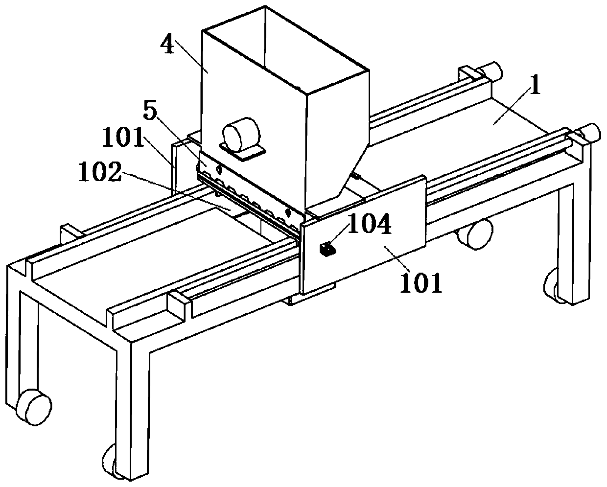
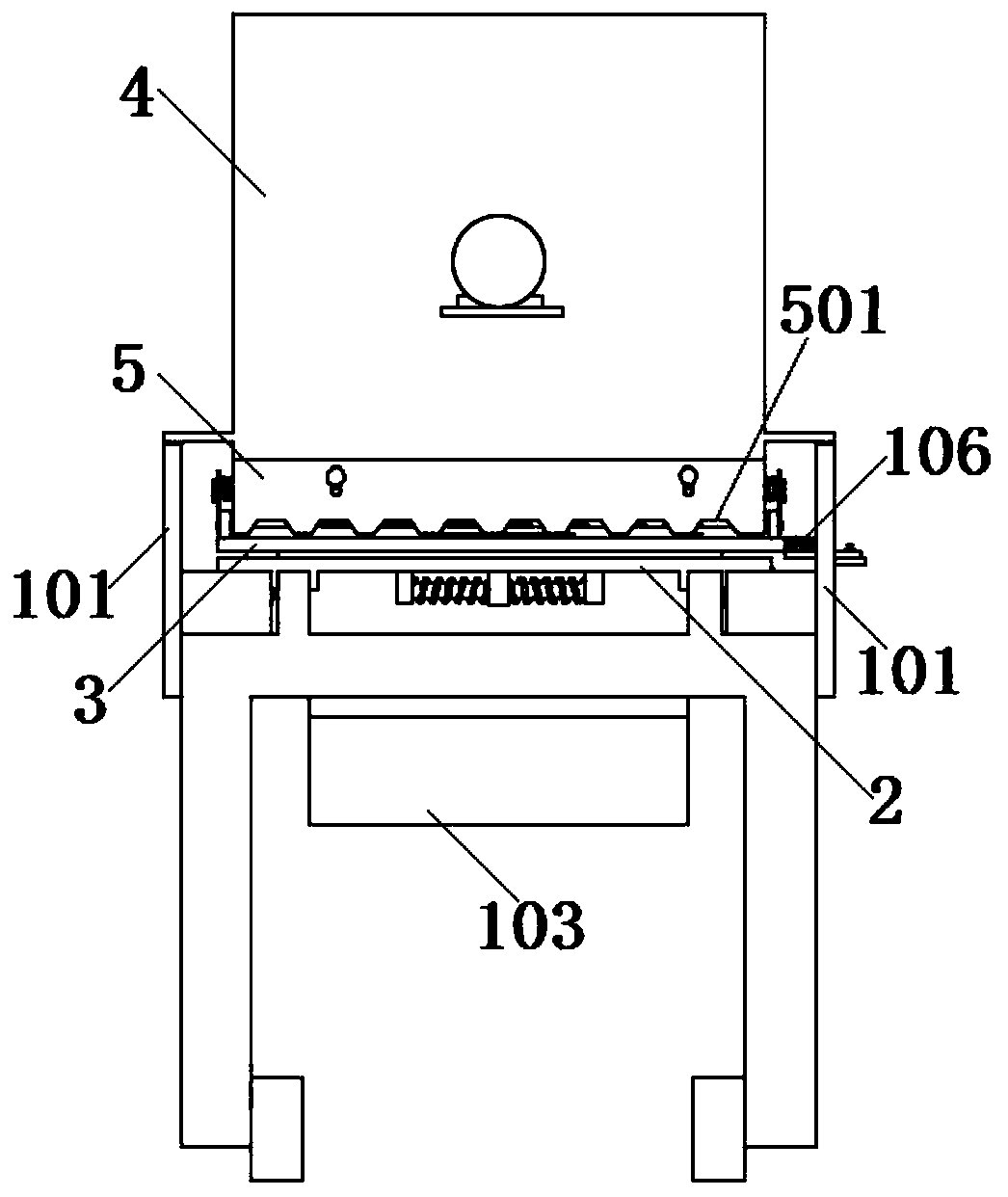
[0035] see figure 1 and 2 As shown, the present invention is a ceramic tile cement application device for building decoration, including a frame; universal wheels are installed on the supporting legs of the frame to facilitate the movement of the frame, so that it can move flexibly according to the construction position. The upper surface of the frame is welded and bolted, and the rectangular mounting plate 1 is installed with two parallel guide rails in the length direction of the upper surface, and the sliding plate 2 is slidably connected to the sliding plate 2 through the guide rail slider mechanism, so that the sliding plate 2 runs along the length direction of the mounting plate 1. Swipe up.

[0036] Such as Figure 7 and 8 As shown, the upper surface of the sliding plate 2 is connected with a smearing platform 3; the opposite side of the mounting plate 1 is fixedly connected with a side plate 101; the two side plates 101 are fixedly connected with a mixing bucket 4 b...

Embodiment 2

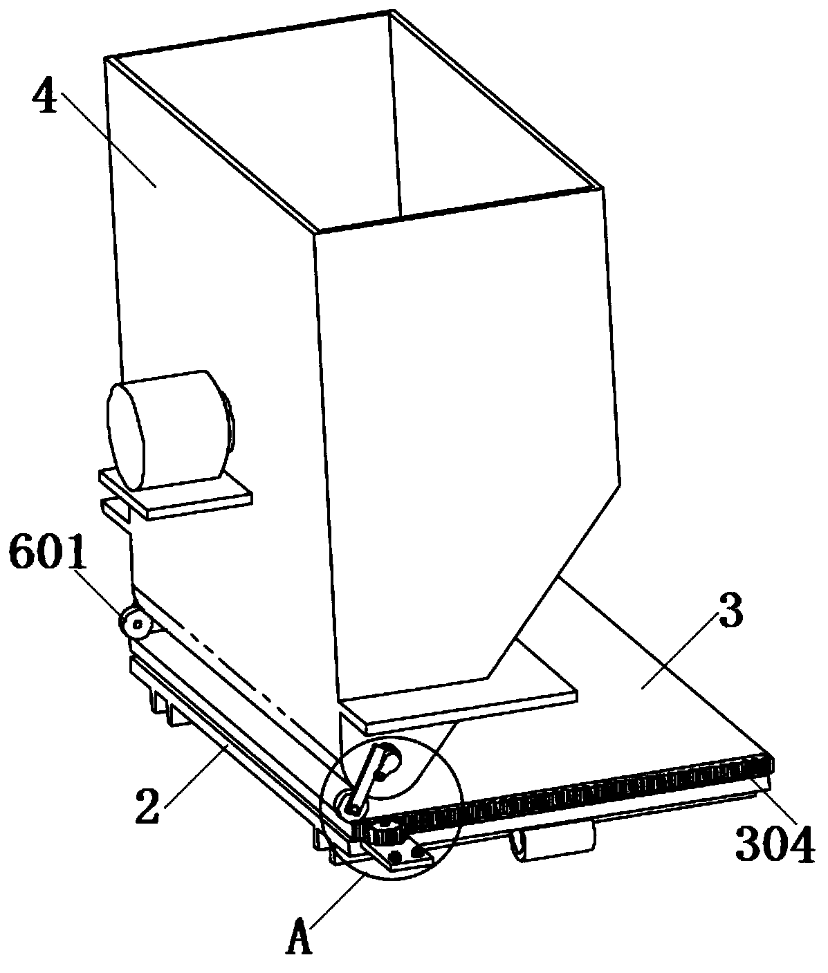
[0049] On the basis of Example 1, as Figure 7 and 8 As shown, the sliding plate 2 is connected to the smearing platform 3 by sliding, such as a guide rail slider mechanism, a slider chute mechanism, etc., and the sliding direction of the smearing platform 3 is perpendicular to the sliding direction of the sliding plate 2 on the mounting plate 1 .

[0050] The surface of the sliding plate 2 is provided with a straight notch 201; the lower surface of the sliding plate 2 is symmetrically welded with two connecting plates 202 relative to the straight notch 201; a guide rod 203 is welded or threaded between the two connecting plates 202; Two return springs 204 are sleeved.

[0051] The lower surface of the smearing platform 3 is welded with a limit block 303; the lower end of the limit block 303 runs through the straight notch 201, and is provided with a through hole for clearance fit with the guide rod 203; the limit block 303 is located between the two return springs 204, so th...


PUM


Abstract

The invention discloses a ceramic tile cement smearing device for architectural decoration, and relates to the technical field of architectural engineering. The ceramic tile cement smearing device comprises a mounting plate and a sliding plate. The sliding plate is connected with a smearing platform. A stirring bucket is fixed to the mounting plate. A plurality of blocking strips and adjusting blocks are fixed to the smearing platform. The outer wall of the stirring bucket is connected with a scraper blade. Discharging openings are formed in the bottom wall of the stirring bucket in an arrayedmanner. An arc-shaped cover plate matched with the inner bottom face of the stirring bucket is rotationally connected in the stirring bucket through a rotary shaft. The two ends of the rotary shaft penetrate through the side wall of the stirring bucket, are sleeved with torsional springs, and are hinged to stirring rods. The upper ends of the stirring rods can abut against the rotary shaft, and the lower ends of the stirring rods are rotationally connected with rollers capable of abutting against the upper surfaces of the adjusting blocks. According to the ceramic tile cement smearing device,by arranging the sliding plate, the smearing platform and the stirring bucket, automatic smearing of ceramic tile cement can be achieved; the problem that the work efficiency of manual smearing is low is solved; and by arranging the scraper blade, the cement on ceramic tiles can be smeared flat, and the problems that existing manual smearing is uneven, and the ceramic tile laying flatness is influenced are solved.

Description

technical field [0001] The invention belongs to the technical field of construction engineering, in particular to a ceramic tile cement application device for building decoration. Background technique [0002] In the decoration process of existing buildings, it is necessary to lay ceramic tiles on the ground or walls, and when laying tiles, cement needs to be placed on the tiles with a bricklaying knife, and then the cement is paved with a bricklaying knife, and finally the tiles can be laid on the ground or on the wall. For shopping malls and office buildings with large building areas, this manual operation process is relatively cumbersome, which seriously affects work efficiency. [0003] In addition, when manually applying cement on the tiles, it is difficult to grasp the amount of cement applied each time, and it is necessary to add or scrape the cement after smoothing, which is a waste of time and cement. At the same time, it is difficult to ensure the uniformity of t...

Claims


Application Information

Patent Timeline
IPC IPC(8): E04F21/02
CPCE04F21/023
Inventor 朱惜惜
Owner 广东正升建筑有限公司
Learn More