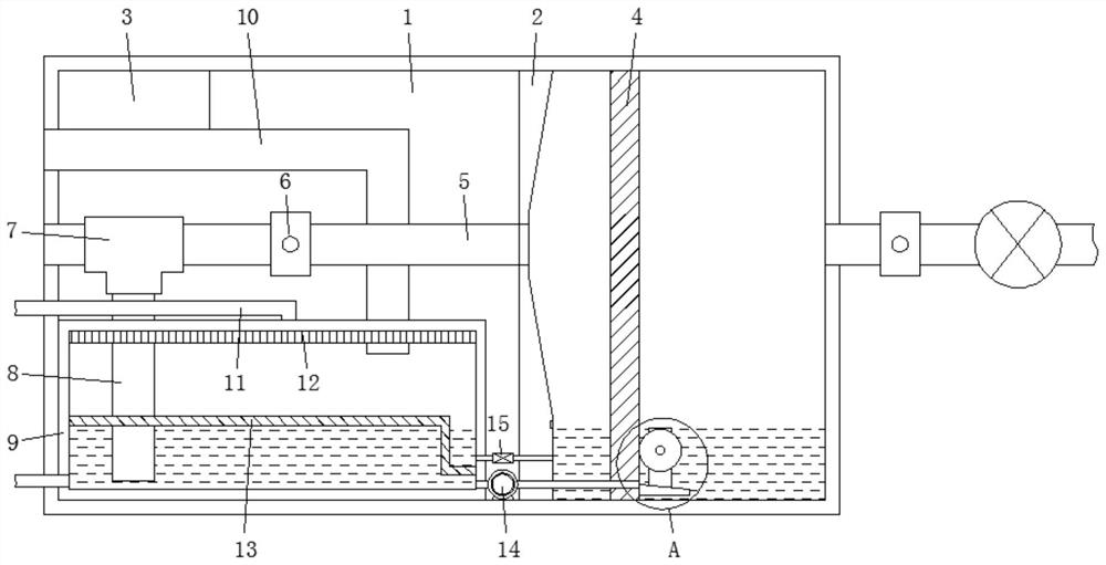
An intelligent electric automatic dust removal device
A technology of electrical automation and dust removal device, which is applied in the direction of combination device, chemical instrument and method, separation method, etc., can solve problems such as troublesome operation, filter blockage, and influence on the dust removal efficiency of the overall device, so as to improve the effect and avoid the phenomenon of dust. Effect
- Summary
- Abstract
- Description
- Claims
- Application Information
AI Technical Summary
Problems solved by technology
Method used
Image
Examples
Embodiment 1
[0028] see Figure 1-Figure 5 As shown, the present invention provides the following technical solutions: an intelligent electric automatic dust removal device, including a control device 3, a device housing 1, and an air intake assembly connected to the air inlet end of the device housing 1, and the device housing 1 is equipped with Partition plate 2, which separates the inside of the device housing 1 to form two processing chambers, and the control device 3 is installed in any one of the processing chambers;
[0029] A first filter screen 4 is installed in one of the processing chambers, and the first filter screen 4 is located between the partition plate 2 and the air inlet assembly;
[0030] A first air outlet pipe 5 is installed in the other processing chamber, and the two ends of the first air outlet pipe 5 respectively pass through the partition plate 2 and the device housing 1. A water tank is installed below the first air outlet pipe 5 in the processing chamber. 9, a...
Embodiment 2
[0038] see Figure 1-Figure 5As shown, the overall structure in this embodiment is used to realize automatic cleaning when the first filter screen 4 is blocked, specifically: a solenoid valve 15 is connected between the partition plate 2 and the water tank 9 through a water guide pipe, and one end of the water guide pipe is located at the second Above the filter screen 13 ; between the clapboard 2 and the water tank 9 is also connected a sewage pump 14 , and the sewage pump 14 has a sewage inlet end passing through the first filter screen 4 , and a sewage discharge end is located below the second filter screen 13 . In this way, the stored water in the water tank 9 can flow into figure 1 In the treatment chamber on the right side of the center, the purpose is to keep the suction roller 16 in a wet state, and the water introduced is the clean water above the second filter screen 13, so it can also avoid secondary pollution to the first filter screen 4 and the sewage pump 14 is ...
PUM
 Abstract
Description
Claims
Application Information
 - R&D
- Intellectual Property
- Life Sciences
- Materials
- Tech Scout
- Unparalleled Data Quality
- Higher Quality Content
- 60% Fewer Hallucinations
Browse by: Latest US Patents, China's latest patents, Technical Efficacy Thesaurus, Application Domain, Technology Topic, Popular Technical Reports.
© 2025 PatSnap. All rights reserved.Legal|Privacy policy|Modern Slavery Act Transparency Statement|Sitemap|About US| Contact US: help@patsnap.com


