Dimming control circuit, chip comprising same and dimming control method

A dimming control circuit and dimming control technology are applied in control circuits, chips and control fields, and can solve the problems of dimming depth and insufficient linearity.

Active Publication Date: 2020-04-10
SHANGHAI BRIGHT POWER SEMICONDUCTOR CO LTD
View PDF12 Cites 0 Cited by
  • Summary
  • Abstract
  • Description
  • Claims
  • Application Information

AI Technical Summary

Problems solved by technology

[0004] The main purpose of the present invention is to solve the problem of insufficient dimming depth and linearity in conventional PWM dimming technology

Method used


Image

  • Dimming control circuit, chip comprising same and dimming control method
  • Dimming control circuit, chip comprising same and dimming control method
  • Dimming control circuit, chip comprising same and dimming control method

Examples


Embodiment Construction

[0033] Relevant detailed description and technical content of the present invention, now just explain as follows with respect to matching drawing:

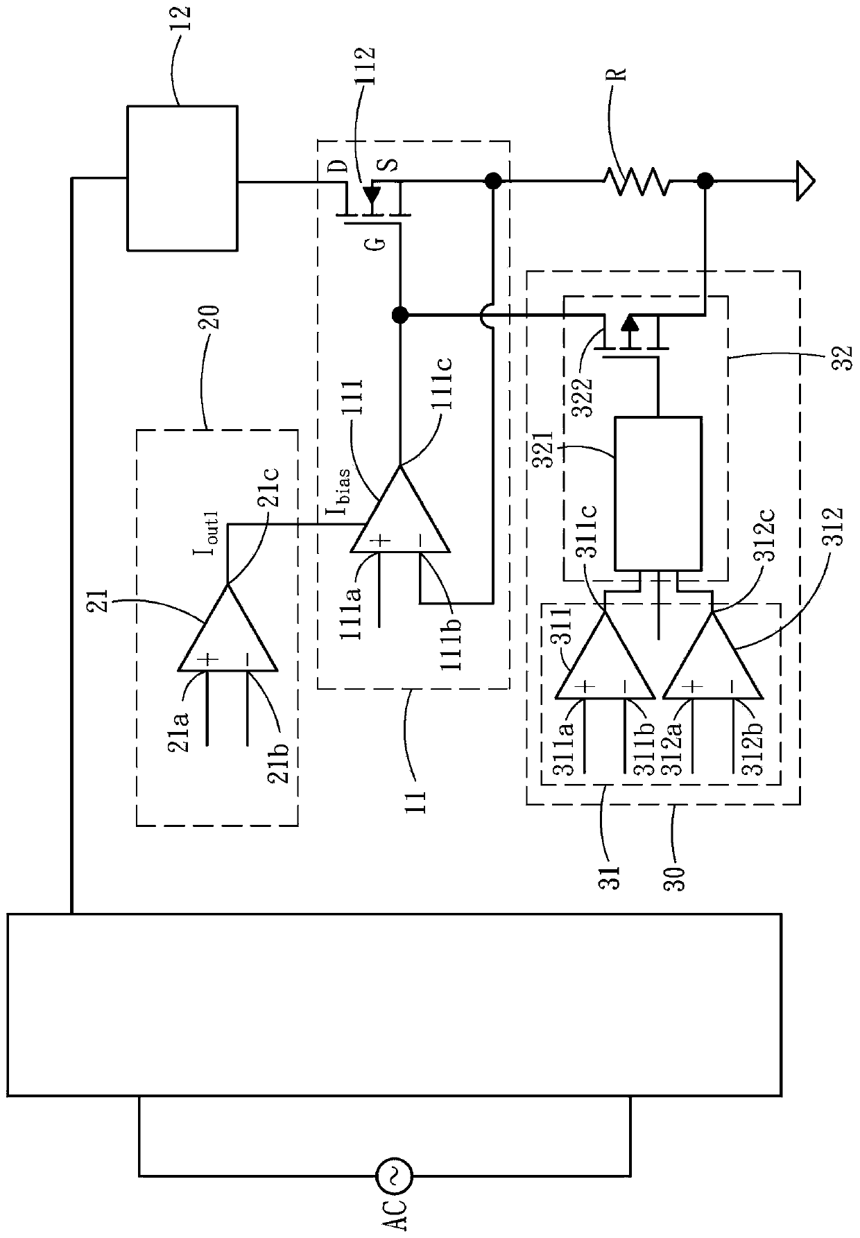
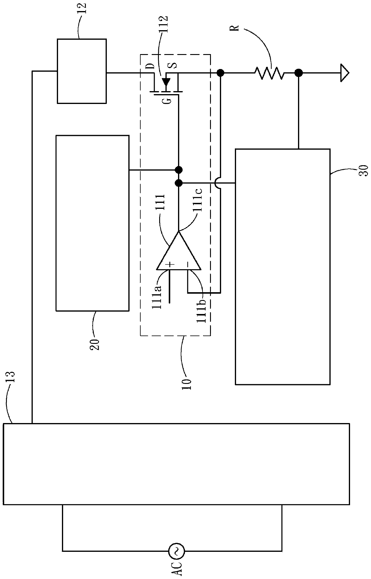
[0034] The present invention discloses a dimming control circuit, a chip containing it and a dimming control method, please refer to figure 1 and figure 2 , is a schematic diagram of a dimming control circuit according to the first embodiment of the present invention. The dimming control circuit is applied to a driving circuit 10, and the driving circuit 10 includes a driving module 11, a load 12 and a rectifying unit 13. The driving module 11 includes a first amplifying unit 111 and a first switching unit 112, the first amplifying unit 111 has a first input terminal 111a, a second input terminal 111b and an output terminal 111c, the first switching unit 112 can be A power switch, such as a Metal Oxide Semiconductor Field-Effect Transistor (MOSFET), but not limited thereto, the power switch can also be one or more triodes. The ...


PUM


Abstract

The invention discloses a dimming control circuit, a chip comprising the same and a dimming control method. The dimming control circuit is applied to a driving circuit. The drive circuit comprises a drive module and a load. The drive module comprises a first amplification unit and a switch unit which is switched between an on state and an off state according to a pulse width modulation signal. Thedimming control circuit comprises a time compensation module. The time compensation module generates a delay signal according to a first time when the current sampling value of the current flowing through the first switch unit rises to a target value and a second time when the current sampling value falls to a closing value, and the time compensation module delays the closing of the switch unit based on the delay signal.

Description

technical field [0001] The invention relates to a control circuit, chip and control method, especially to a control circuit, chip and control method for dimming. Background technique [0002] Among light-emitting diode (Light-emitting diode, LED) dimming control methods, Pulse Width Modulation (Pulse Width Modulation, PWM) is a preferred choice and has become a mainstream technology. The traditional PWM dimming method is to change the pulse width between 0% and 100% to adjust the average current flowing through the LED load to realize the dimming function. [0003] However, as the market and applications gradually increase the requirements for LED dimming, PWM dimming also exposes the problems of dimming depth and insufficient linearity. According to the current technology, in terms of dimming depth, the minimum brightness of PWM dimming is about 5%, so it cannot cover the application range of low brightness; in terms of linearity, when it is in the low brightness range, be...

Claims


Application Information

Patent Timeline
IPC IPC(8): H05B45/325H05B45/10
CPCY02B20/40
Inventor 孙顺根
Owner SHANGHAI BRIGHT POWER SEMICONDUCTOR CO LTD
Why Eureka
Try Eureka